Page 13
XC16 SERIES
3. Attach the stubbed end of the TXV to the liquid line
orifice housing. Finger tighten and use an appropriately
sized wrench to turn an additional 1/2 turn clockwise
as illustrated in figure 22, or 20 ft−lb.
4. Place the remaining Teflon ring around the other end
of the TXV. Lightly lubricate connector threads and
expose surface of the Teflon ring with refrigerant oil.
5. Attach the liquid line assembly to the TXV. Finger
tighten and use an appropriately sized wrench to turn
an additional 1/2 turn clockwise as illustrated in figure
22, or 20 ft−lb.
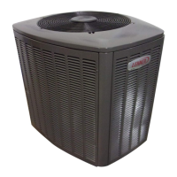
6. Attach the suction line sensing bulb in the proper
orientation as illustrated in figure 25 using the clamp
and screws provided.
NOTE − Insulating the sensing bulb once installed may be
required when the bulb location is external to the coil
casing.
ON 7/8" AND LARGER LINES,
MOUNT SENSING BULB AT
EITHER THE 4 OR 8 O’CLOCK
POSITION. NEVER MOUNT
ON BOTTOM OF LINE.
12
ON LINES SMALLER THAN
7/8", MOUNT SENSING BULB
AT EITHER THE 3 OR 9
O’CLOCK POSITION.
12
BULB
SUCTION LINE
SUCTION LINE
NOTE − NEVER MOUNT ON
BOTTOM OF LINE.
BULB
BULB
BULB
Figure 25. TXV Sensing Bulb Installation
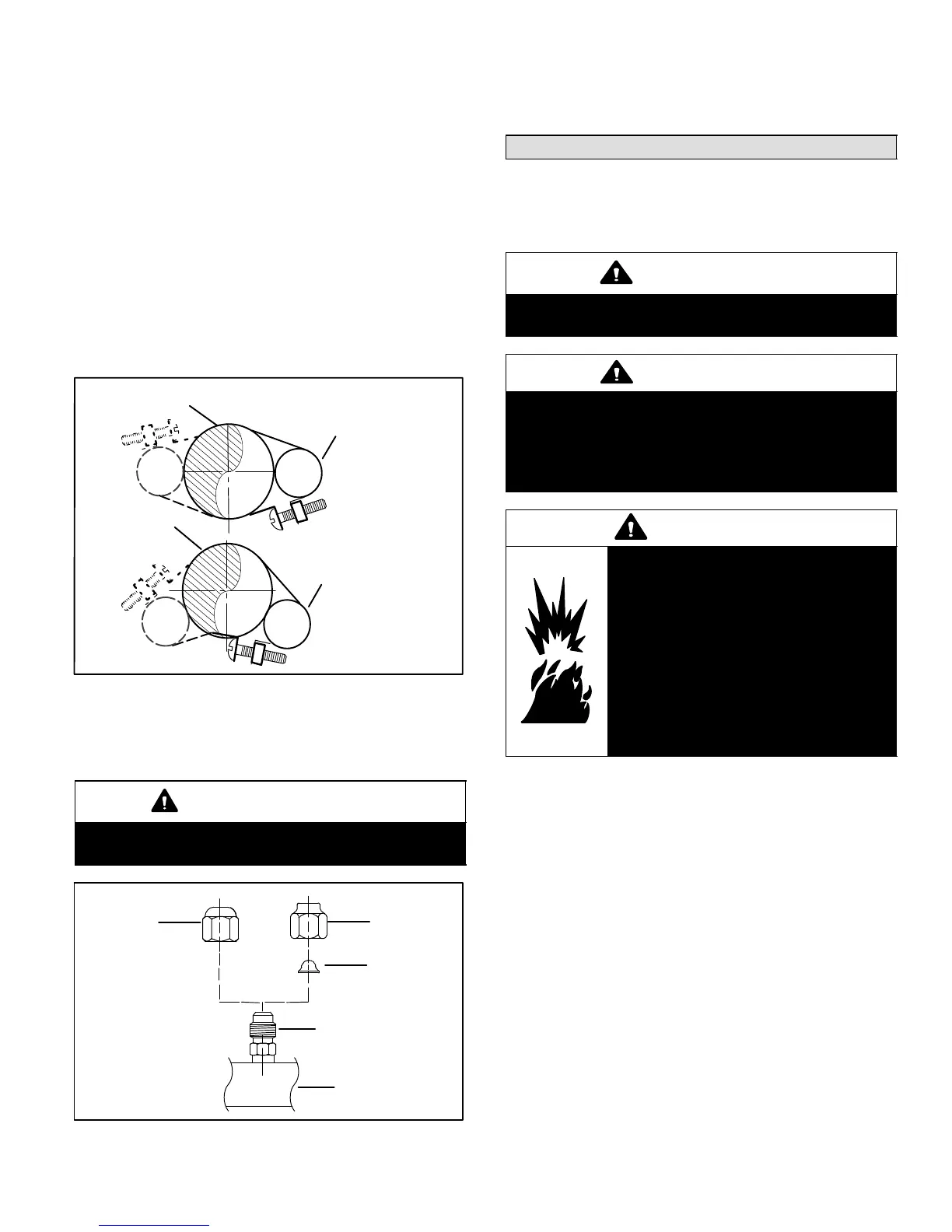
7. Remove and discard either the flare seal cap or flare
nut with copper flare seal bonnet from the equalizer
line port on the suction line as illustrated in figure 26.
IMPORTANT
When removing the flare nut, ensure that the copper
flare seal bonnet is removed.
SUCTION LINE
FLARE NUT
COPPER
FLARE SEAL
BONNET
MALE BRASS EQUALIZER
LINE FITTING
FLARE SEAL
CAP
OR
Figure 26. Copper Flare Seal Bonnet Removal
8. Connect the equalizer line from the TXV to the
equalizer suction port on the suction line. Finger
tighten the flare nut plus 1/8 turn (7 ft−lbs) as illustrated
in figure 22.
Testing for Leaks
After the line set has been connected to both the indoor
and outdoor units, check the line set connections and
indoor unit for leaks. Use the following procedure to test for
leaks:
IMPORTANT
Leak detector must be capable of sensing HFC
refrigerant.
WARNING
Refrigerant can be harmful if it is inhaled.
Refrigerant must be used and recovered
responsibly.
Failure to follow this warning may result in personal
injury or death.
WARNING
Fire, Explosion and Personal Safety
Hazard.
Failure to follow this warning could
result in damage, personal injury or
death.
Never use oxygen to pressurize or
purge refrigeration lines. Oxygen,
when exposed to a spark or open
flame, can cause damage by fire and/
or an explosion, that could result in
personal injury or death.
1. Connect an HFC−410A manifold gauge set high
pressure hose to the suction valve service port.
NOTE − Normally, the high pressure hose is connected to
the liquid line port; however, connecting it to the suction
port better protects the manifold gauge set from high
pressure damage.
2. With both manifold valves closed, connect the cylinder
of HFC−410A refrigerant to the center port of the
manifold gauge set. Open the valve on the HFC−410A
cylinder (suction only).
3. Open the high pressure side of the manifold to allow
HFC−410A into the line set and indoor unit. Weigh in
a trace amount of HFC−410A. [A trace amount is a
maximum of two ounces (57 g) refrigerant or three
pounds (31 kPa) pressure]. Close the valve on the
HFC−410A cylinder and the valve on the high pressure
side of the manifold gauge set. Disconnect the
HFC−410A cylinder.
4. Connect a cylinder of dry nitrogen with a pressure
regulating valve to the center port of the manifold
gauge set.

 Loading...