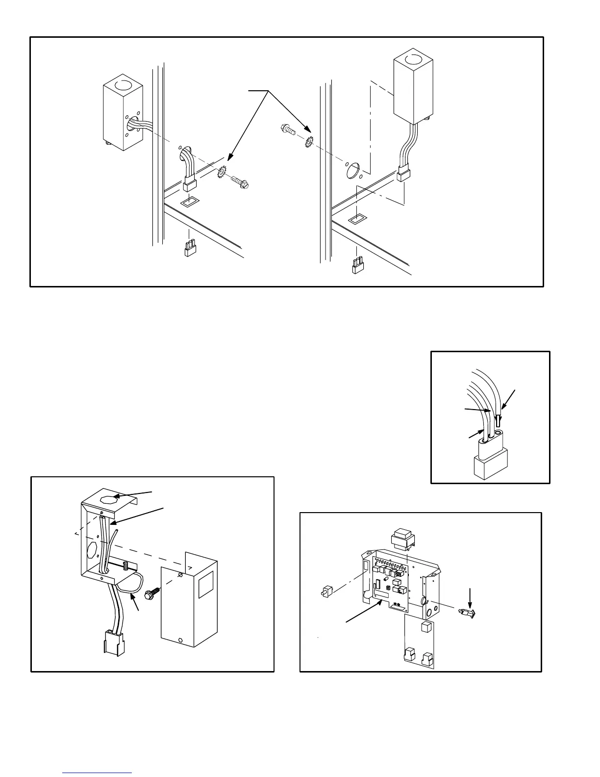
BLACK
WHITE
NEUTRAL
BROWN
J69
INSTALLING BROWN
ACCESSORY WIRE TO J69
FIGURE 4
Page 6
FIGURE 2
MAKEUP BOX INSTALLATION
MAKEUP BOX
MAKEUP BOX
UNIT
CABINET
Box may be installed inside or outside cabinet and
may be installed on left side or right side of cabinet
JACK J69
PLUG P69
BLOWER MULLION
BLOWER MULLION
OUTSIDE INSTALLATION
INSIDE INSTALLATION
Line Voltage Enters MakeUp
Box Through Side Of Unit and
J69 Passes Through Bottom
Knockout in MakeUp Box.
Line Voltage Enters Through
Knockout In MakeUp Box.
J69 Passes Through Side
Knockout Into Side Of Unit.
STAR WASHERS
MUST BREAK
PAINT ON UNIT
CABINET FOR
PROPER GROUND.
I−UNIT COMPONENTS
G32 unit components are shown in figure 1. The gas valve,
ignition control and burners can be accessed by removing the
burner access panel. The blower and blower controls can be
accessed by removing the blower access door.
G32 units are designed for bottom and side return air. The
panels are designed to be knockedout (bottom return) or
cutout (side return) as required for return air duct connec
tion.
A−MakeUp Box (Figure 3)
The line voltage makeup box is shown in figure 3. The box
may be installed inside or outside the unit and may be installed
on the unit left or right side (figure 2).
FIGURE 3
MAKEUP BOX
BOX
COVER
JACK J69
to blower deck
TO BLOWER MULLION
POWER ENTRY KNOCKOUT
120V LINE VOLTAGE
PIGTAIL CONNECTIONS
UNIT
GROUND
Box may be installed inside or outside unit. See Figure 2.
An accessory (brown) output wire is provided with the make
up box. The wire provides a 120V connection for optional ac
cessories such as electronic air cleaner or humidifier. If used,
the wire is field installed in J69 jack plug by inserting the pin of
the brown wire into the open
socket of the jack. See figure 4.
120V accessories rated up to 4
amps total may be connected
to this wire. The neutral leg of
the accessory is connected to
the neutral white wire in the
makeup box. The accessory
terminal is energized whenev
er the blower is in operation.
B−Control Box Components
G32−1 / −4 UNIT CONTROL BOX
FIGURE 5
CIRCUIT
BREAKER
SURELIGHT
CONTROL
DOOR
INTERLOCK
SWITCH
TRANSFORMER
TWOSTAGE
CONTROL
BOARD
 Loading...


