Page 10
WARNING
Improper installation of the furnace can result in per-
sonal injury or death. Combustion and flue products
must never be allowed to enter the return air system
or air in the living space. Use sheet metal screws and
joint tape to seal return air system to furnace.
In platform installations with furnace return, the fur-
nace should be sealed airtight to the return air ple-
num. A door must never be used as a portion of the
return air duct system. The base must provide a
stable support and an airtight seal to the furnace. Al-
low absolutely no sagging, cracks, gaps, etc.
For no reason should return and supply air duct sys-
tems ever be connected to or from other heating de-
vices such as a fireplace or stove, etc. Fire, explo-
sion, carbon monoxide poisoning, personal injury
and/or property damage could result.
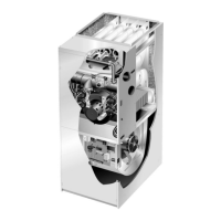
Upflow Applications
The G61MPV gas furnace can be installed as shipped in
the upflow position. Refer to figure 8 for clearances.
Installation Clearances
Top
Bottom (Floor)
Left Side
Right Side
Top/Plenum 1 in. (25 mm)
*Front 0
Back 0
Sides 0†
Vent 0
Floor 0‡
*Front clearance in alcove installation must be 24 in. (610 mm).
Maintain a minimum of 24 in. (610 mm) for front service access.
†Allow proper clearances to accommodate condensate trap and
vent pipe installation.
‡For installations on a combustible floor, do not install the furnace
directly on carpeting, tile or other combustible materials other
than wood flooring.
FIGURE 8
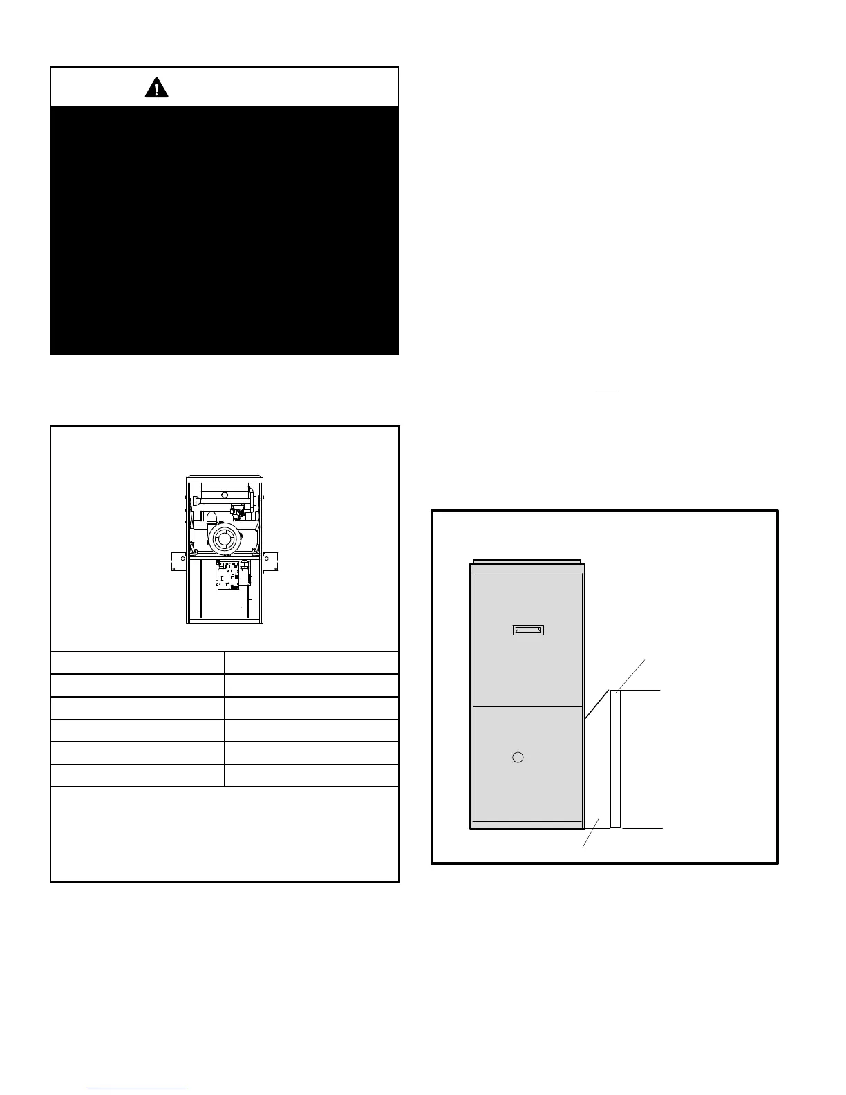
Return Air −− Upflow Units
Return air can be brought in through the bottom or either
side of the furnace installed in an upflow application. If the
furnace is installed on a platform with bottom return, make
an airtight seal between the bottom of the furnace and the
platform to ensure that the furnace operates properly and
safely. The furnace is equipped with a removable bottom
panel to facilitate installation.
Markings are provided on both sides of the furnace cabinet
for installations that require side return air. Cut the furnace
cabinet at the maximum dimensions shown on page 2.
NOTE − When air volumes over 1800 cfm (850 L/s) are
required with 60C or 60D models in an upflow applica-
tion, the following return air options are available:
1 − Return air from single side with transition which will
accommodate 20 x 25 x 1 in. (508 x 635 x 25 mm) air filter.
(Required to maintain proper air velocity.) See figure 9.
2 − Return air from single side with optional RAB Return
Air Base. See figure 11.
3 − Return air from bottom.
4 − Return air from both sides.
5 − Return air from bottom and
one side.
Refer to Engineering Handbook for additional information.
G61MPV applications which include side return air and
a condensate trap installed on the same side of the
cabinet require either a return air base or field−fabri-
cated transition to accommodate an optional IAQ ac-
cessory taller than 14.5".
Side Return Air
(with transition and filter)
FIGURE 9
Return Air
Plenum
Transition
20" X 25" X 1"
(508mm X635mm X 25mm)
Air Filter
Removing the Bottom Panel
Remove the two screws that secure the bottom cap to the
furnace. Pivot the bottom cap down to release the bottom
panel. Once the bottom panel has been removed, reinstall
the bottom cap. See figure 10.
 Loading...