Page 57
Manifold Pressure Measurement & Adjustment
Supply Pressure Measurement
A threaded plug on the inlet side of the gas valve provides
access to the supply pressure tap. Remove the threaded
plug, install a field−provided barbed fitting and connect a
manometer to measure supply pressure. Replace the
threaded plug after measurements have been taken.
Manifold Pressure Measurement
To correctly measure manifold pressure, the differential
pressure between the positive gas manifold and the nega-
tive burner box must be considered. Use pressure test
adapter kit (available as Lennox part 10L34) to assist in
measurement.
1 − Remove the threaded plug from the outlet side of the
gas valve and install a field−provided barbed fitting.
Connect test gauge +" connection to barbed fitting to
measure manifold pressure.
2 − Tee into the gas valve regulator vent hose and connect
test gauge −" connection.
3 − Start unit on low heat (68% rate) and allow 5 minutes
for unit to reach steady state.
4 − While waiting for the unit to stabilize, notice the flame.
Flame should be stable and should not lift from burner.
Natural gas should burn blue.
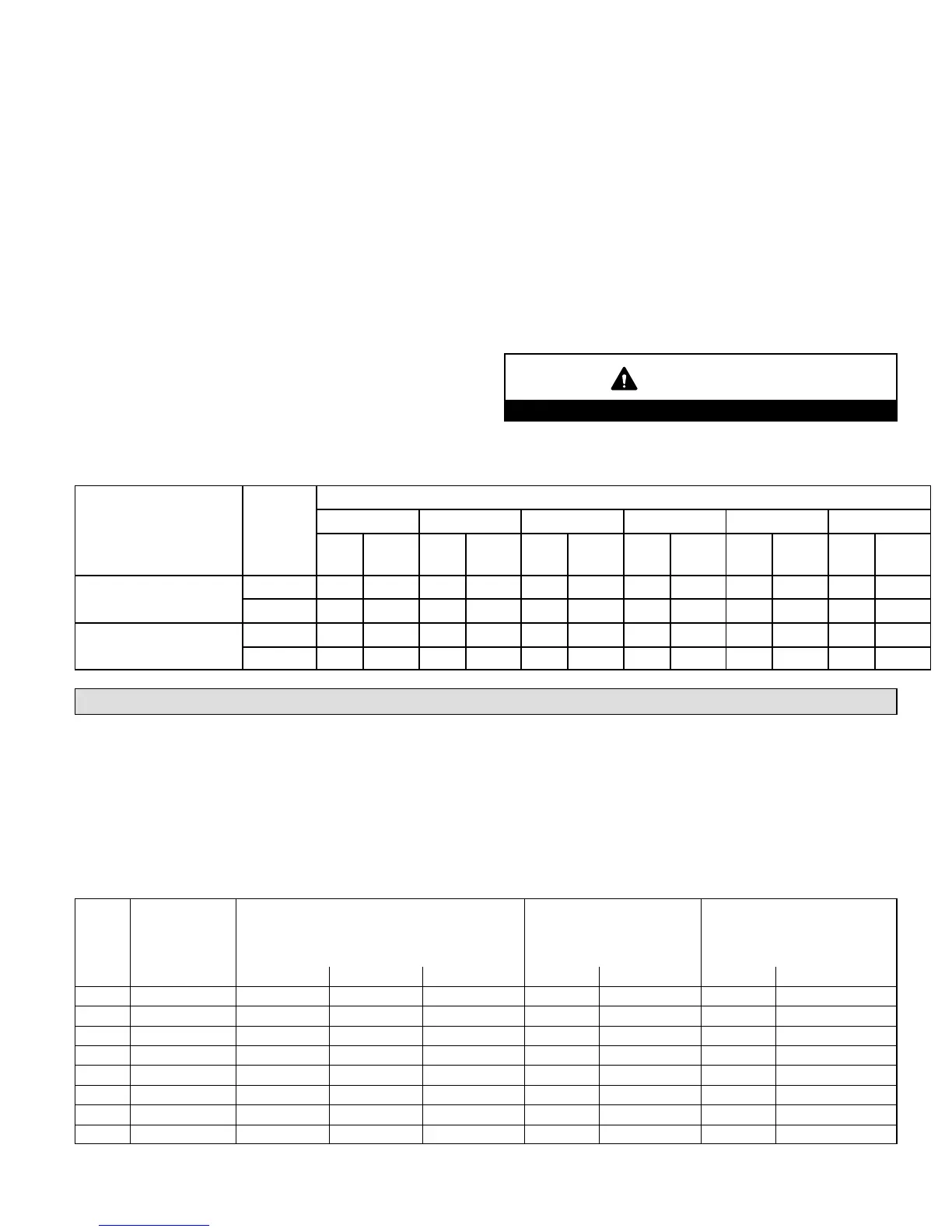
5 − After allowing unit to stabilize for 5 minutes, record
manifold pressure and compare to value given in table
32.
6 − Repeat steps 3, 4 and 5 on high heat.
NOTE − Shut unit off and remove manometer as soon as an
accurate reading has been obtained. Take care to remove
barbed fitting and replace threaded plug.
CAUTION
Do not attempt to make adjustments to the gas valve.
TABLE 32
Manifold Pressure (Outlet)
Model Number
Fuel
Altitude (feet)
0−2000 2001−4500 4501−5500 5501−6500 6501−7500 7501−10000
Low
Fire
High
Fire
Low
Fire
High
Fiire
Low
Fire
High
Fiire
Low
Fire
High
Fiire
Low
Fire
High
Fiire
Low
Fire
High
Fiire
045, 070, 071, 090,
110, 135
Natural 1.7 3.5 1.7 3.5 1.7 3.5 1.7 3.5 1.7 3.5 1.7 3.5
Propane 4.9 10.0 4.9 10.0 4.9 10.0 4.9 10.0 4.9 10.0 4.9 10.0
091, 111
Natural 1.7 3.5 1.7 3.4 1.7 3.3 1.7 3.2 1.7 3.1 1.7 3.5
Propane 4.9 10.0 4.9 10.0 4.9 10.0 4.9 10.0 4.9 10.0 4.9 10.0
High Altitude Information
NOTE − In Canada, certification for installations at eleva-
tions over 4500 feet (1372 m) is the jurisdiction of local au-
thorities.
The manifold pressure may require adjustment to ensure
proper operation at higher altitudes. Refer to table 32 for
manifold pressure and table 33 for required pressure
switch changes and conversion kits at varying altitudes.
The combustion air pressure switches are factory−set and
require no adjustment.
NOTE − A natural to L.P. propane gas changeover kit is nec-
essary to convert this unit. Refer to the changeover kit
installation instruction for the conversion procedure.
TABLE 33
Conversion Kit Requirements
Input
High Altitude
Orifice Kit
Natural Gas
Only
High Altitude Pressure Switch Kit
ORDER TWO EACH
LPG/Propane Kit LPG/Propane to
Natural Gas Kit
7501−10,000 ft. 2000−4500 ft. 4501−7500 ft. 7501−10,000 ft. 0−7500 ft. 7501−10,000 ft. 0−7500 ft.
1
7501−10,000 ft.
−045 44W51 − − − − − − − − − 44W48 44W50 44W49 44W49 + 44W51
−070 44W51 − − − − − − 56M23 44W48 44W50 44W49 44W49 + 44W51
−071 44W51 75M22 75M22 56M21 44W48 44W50 44W49 44W49 + 44W51
−090 44W51 − − − 75M22 56M21 44W48 44W50 44W49 44W49 + 44W51
−091 47M82 26W85 26W85 26W86 44W48 44W50 44W49 44W49 + 47M82
−110 44W51 − − − 56M23 75M22 44W48 44W50 44W49 44W49 + 44W51
−111 47M82 56M22 56M22 56M23 44W48 44W50 44W49 44W49 + 47M82
−135 44W51 − − − 56M93 56M93 44W48 44W50 44W49 44W49 + 44W51
1
High Altitude Orifice Kit is required and must be ordered separately for applications from 7501 to 10,000 ft.
 Loading...