Page 20
NOTE − The flue collar on all models is sized to accommo-
date 2" Schedule 40 flue pipe. When vent pipe which is
larger than 2" must be used in an upflow application, a 2"
elbow must be applied at the flue collar in order to proper-
ly transition to the larger diameter flue pipe. This elbow
must be added to the elbow count used to determine ac-
ceptable vent lengths. Assign an equivalent feet value to
this elbow according to the larger size pipe being used.
Contact the Application Department for more information
concerning sizing of vent systems which include multiple
pipe sizes.
Use the following steps to correctly size vent pipe diameter.
Refer to Vent Pipe Size Determination Worksheet on
page 65.
1 − Determine the vent termination and its corresponding
equivalent feet value according to table 5.
2 − Determine the number of 90° elbows required for both
indoor and outdoor (e.g. snow riser) use. Calculate the
corresponding equivalent feet of vent pipe.
3 − Determine the number of 45° elbows required for both
indoor and outdoor use. Calculate the corresponding
equivalent feet of vent pipe.
4 − Determine the length of straight pipe required.
5 − Add the total equivalent feet calculated in steps 1
through 4 and compare that length to the maximum
values given in table 7 for the proposed vent pipe di-
ameter. If the total equivalent length required exceeds
the maximum equivalent length listed in the appropri-
ate table, evaluate the next larger size pipe.
IMPORTANT
Do not use screens or perforated metal in exhaust
terminations. Doing so will cause freeze−ups and
may block the terminations.
TABLE 6
MINIMUM VENT PIPE LENGTHS
G61MPV
MODEL
MIN. EQUIV.
VENT LENGTH
EXAMPLE
045, 070,
071, 090,
091
15 ft.*
5 ft. plus 2 elbows of 2", 2−1/2", 3"
or 4" diameter pipe
110
5 ft. plus 2 elbows of 2−1/2" 3" or 4"
diameter pipe
135***
5 ft. plus 2 elbows of 3" or 4"
diameter pipe
*Any approved termination may be added to the minimum equivalent length
listed.
**G61MPV−60C−110 and −111 must have 90° street ell (supplied or field re-
placement Canadian kit) installed directly into unit flue collar.
***G61MPV−60D−135 must have 3" to 2" reducing ell (supplied or field replace-
ment Canadian kit) installed directly into unit flue collar.
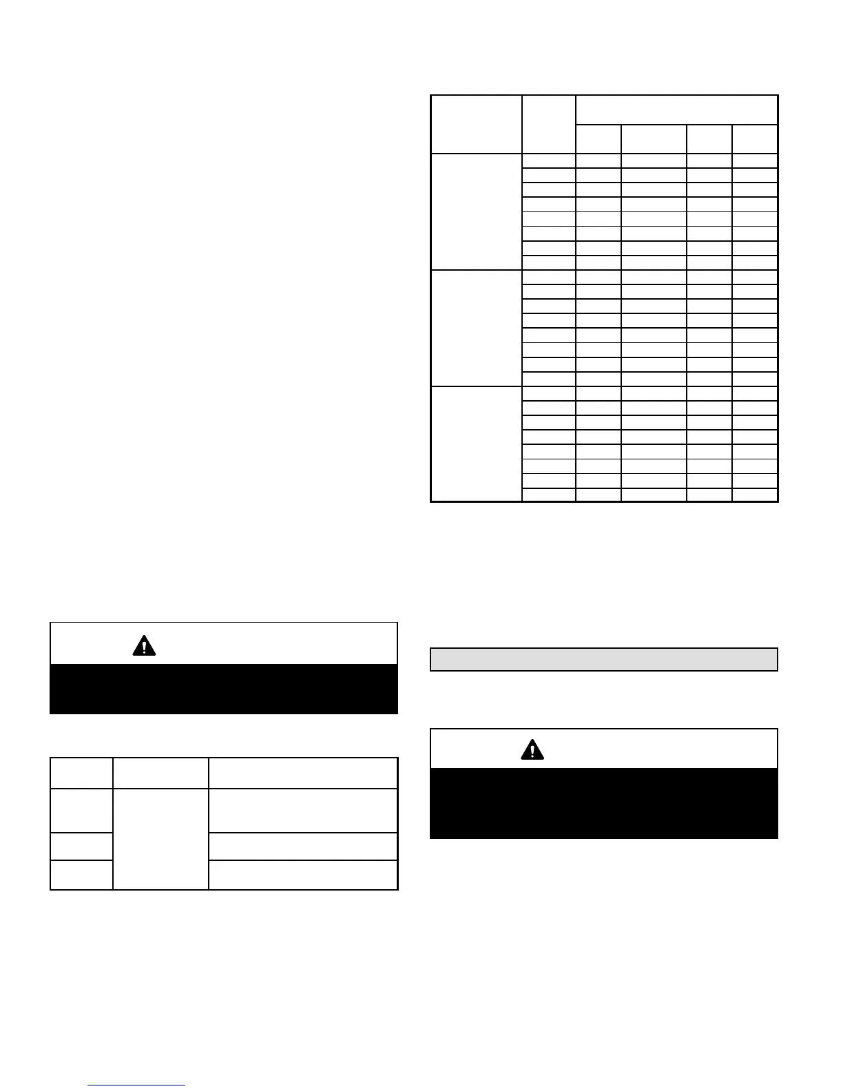
TABLE 7
MAXIMUM VENT PIPE LENGTHS
ALTITUDE
G61MPV
MODEL
MAXIMUM EQUIVALENT VENT
LENGTH FEET
2"
PIPE
2−1/2"
PIPE
3"
PIPE
4"
PIPE
0 − 4500
(0 − 1371 m)
045 59 65 77 234
070 59 65 78 214
071† 59 65 78 214
090 26 42 72 204
091† 26 42 72 204
110* n/a 32 72 179
111*† n/a 32 72 179
135**‡ n/a n/a 61 160
4501−7500
(1372−2286 m)
045 59 65 77 234
070 59 65 78 214
071† 59 65 78 214
090 26 42 72 204
091† 26 42 72 204
110* n/a 32 72 179
111*† n/a 32 72 179
135**‡ n/a n/a 46 160
7501 − 10000
(2287 − 3048 m)
045 59 65 77 234
070 59 65 78 214
071† 59 65 78 214
090 26 42 72 204
091† 26 42 72 204
110* n/a 32 72 179
111*† n/a 32 72 179
135**‡ n/a n/a 46 160
n/a −− Not allowed.
*G61MPV−60C−110 and −111 must have 90° street ell (supplied or field replace-
ment Canadian kit) installed directly into unit flue collar.
**G61MPV−60D−135 must have 3" to 2" reducing ell (supplied or field replace-
ment Canadian kit) installed directly into unit flue collar.
†On G61MPV−071, −091 and −111 units, sweep elbows must be used
for all 90° elbows in the venting system when 2", 2−1/2" or 3" vent
pipe is used. Sweep elbows are recommended for use in vent sys-
tems of other G61MPV units.
‡On G61MPV−60D−135 units, sweep elbows must be used for all 90° el-
bows in the vent system when 3" vent pipe is used.
Joint Cementing Procedure
All cementing of joints should be done according to the
specifications outlined in ASTM D 2855.
WARNING
DANGER OF EXPLOSION!
Fumes from PVC glue may ignite during system
check. Allow fumes to dissipate for at least 5 minutes
before placing unit into operation.
1 − Measure and cut vent pipe to desired length.
2 − Debur and chamfer end of pipe, removing any ridges
or rough edges. If end is not chamfered, edge of pipe
may remove cement from fitting socket and result in a
leaking joint.
3 − Clean and dry surfaces to be joined.
4 − Test fit joint and mark depth of fitting on outside of pipe.
 Loading...