10-Installtheroomthermostataccordingto theinstruc-
tionsprovidedwiththethermostat,Seetable10for
thermostatconnections.If the furnace is being
matchedwitha heatpump,referto the instruction
packagedwiththedualfuelthermostat,
ThermostatSelection
TheG71MPPisdesignedtooperateinavariablerateca-
pacitymodeusingatwo-stagethermostat.TheG71MPP
willautomaticallyadjustfiringratebaseduponthermostat
cycletimes,Foroptimalperformance,Lennoxrecom-
mendsuseof a highqualityelectronicdigitalthermostat
withadjustablesettingsfor1ststage/ 2rid stage on / off dif-
ferentials and adjustable stage timers.
Lennox recommends the following two-stage thermostat
set-up for optimal variable rate capacity mode:
First heat stage differential set to 1/2 to 1 degree F; second
heat stage differential set to 1/2 or 1 degree F; second heat
stage upstage timer disabled, or set to maximum (1 hr mini-
mum).
Indoor Blower Speeds
1 - When the thermostat is set to "FAN ON," the indoor
blower will run continuously at a percentage of the sec-
ond-stage cooling speed when there is no cooling or
heating demand. The percentage is set using DIP
switches 6 and 7,
2 - When the G71MPP is running in the heating mode, the
integrated control will automatically adjust the blower
speed to match the furnace firing rate. This speed can
be adjusted up or down by 7,5% or 15% using DIP
switches 14 through 16 for the low heat speed and 17
through 19 for the high heat speed.
3 - When there is a cooling demand, the indoor blower will
run on the cooling speed designated by the positions
of DIP switches 8 through 11,
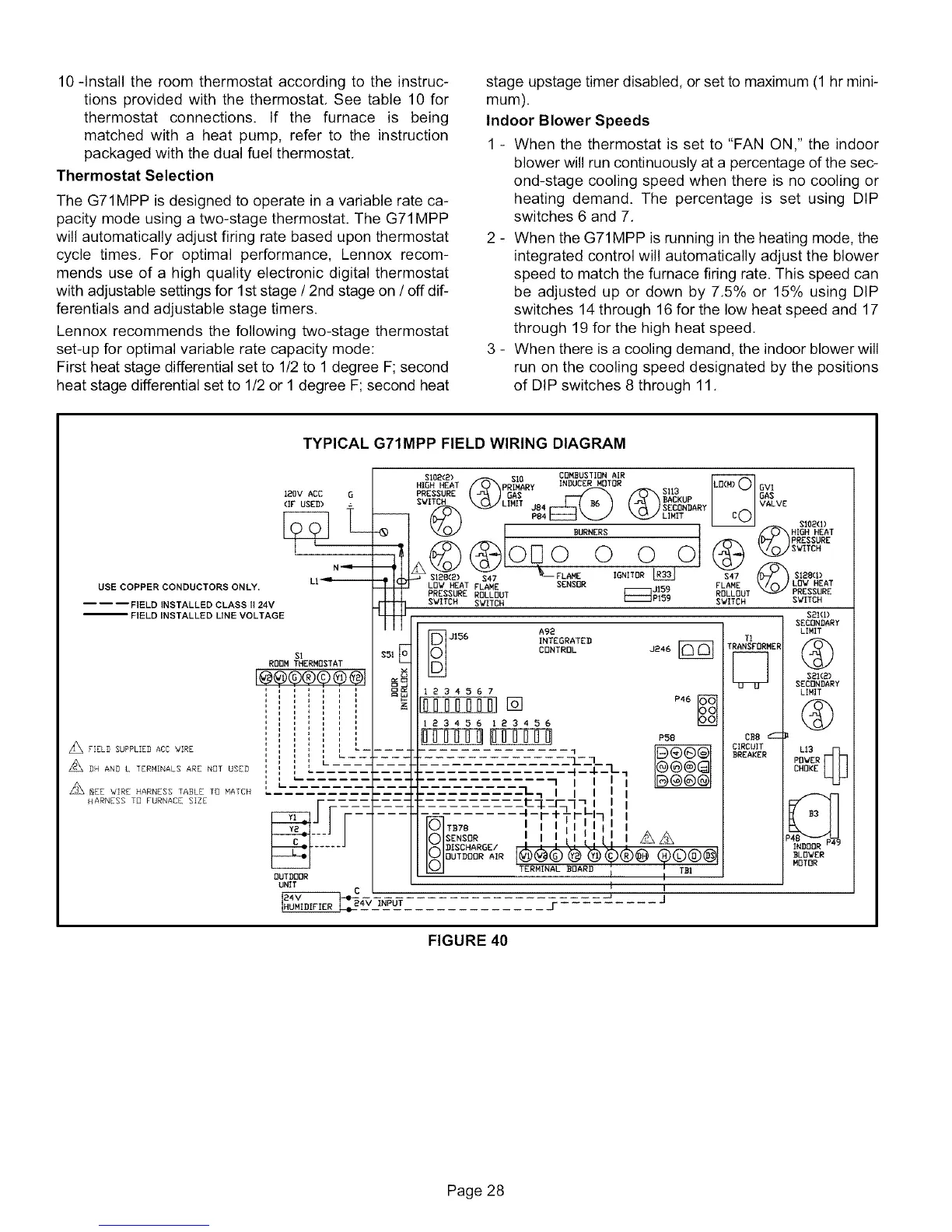
TYPICAL G71MPP FIELD WIRING DIAGRAM
USE COPPER CONDUCTORS ONLY.
I I I FIELD INSTALLED CLASS 0 24V
FIELD INSTALLED LINE VOLTAGE
FIELD SUPPLIED ACC WIRE
z_ DH AND L TERHINALS ARE NOT USED
_GEE WIRE HARNESS TASLE TO MATCH
HARNESS T8 FURNACE SIZE
120V ACC G
LI -_--ili
$102(2) COMBUSTION AIR
PREGGUREGAG GlIB
SWITCH LIMIT BACKUP GAS
SECONDARY VALVE
LIMIT cO
BURNERS HIGH HEAT
PRESSURE
@ SWITCH
-_ $1£8(G) _FLAME IGNITOR L_ _--_ $128(1)
LOW HEAT FLAME SENSOR 3159 FLAME /k_ LOW HEAT
PRESSURE ROLLOUT _P159 RDLLDUT PRESSURE
SWITCH SWITCH SWITCH SWITCH
s51E
A92
E)-3156 INTEGRATED
0 CONTROL 3246
D
-i
I
I
I
$1
ROOM THERMOSTAT
I@@@®©@@I _
j " ' t3c_
',
i
,,
,,
i
i
Ii L .......
i
I ....
OUTDOOR
UNIT
C
_24_ INPUT
BF n [] P46
23456 183456
L-:___
I--4---
'I I I
L_ I I I
L_-_77 I
_),_)TO78 I I I I
SENSOR I I I 11 Ill II Z_ _
DDISCHAROE' 90DQ
TERHINAL BOARD
t I
I i
r ..........
TI
TRANSFORMER
CB8 'I--
CIRCUIT
BREAKER
SOl(If
SECONDARY
LIMIT
®
821(2)
SECONDARY
LIMIT
®
L1B @
POWER
CHOKE
B3
INDOOR F _)
BLOWER
MOTOR
FIGURE 40
Page 28
 Loading...