Page 49
E−Check Manifold Pressure
To correctly measure manifold prressure, the differential
pressure between the positive gas manifold and the nega-
tive burner box must be considered. Use pressure test
adapter kit (available as Lennox part 10L34) to assist in
measurement.
1 − Connect test gauge +" connection to manifold pres
sure tap on the gas vavle.
2 − Tee into the gas valve regulator vent hose and con-
nect test gauge −" connection.
3 − Start unit on low heat (40%) rate) and allow 5 min-
utes for unit to reach steady state.
4 − While waiting for the unit to stabilize, notice the
flame. Flame should be stable and should not lift from
burnere. Natural gas should burn blue.
5 − After allowing unit to stablize for 5 minutes, record
manifold pressure and compare to value given in table
42.
6 − Repeat stpes 3, 4 and 5 on high fire.
CAUTION
Do not attempt to make adjustments to the gas valve.
F− Proper Gas Flow (Approximate)
1 − Operate unit at least 15 minutes before checking gas
flow. Determine the time in seconds for one revolu-
tions of gas through the meter. A portable LP gas me-
ter (17Y44) is available for LP applications.
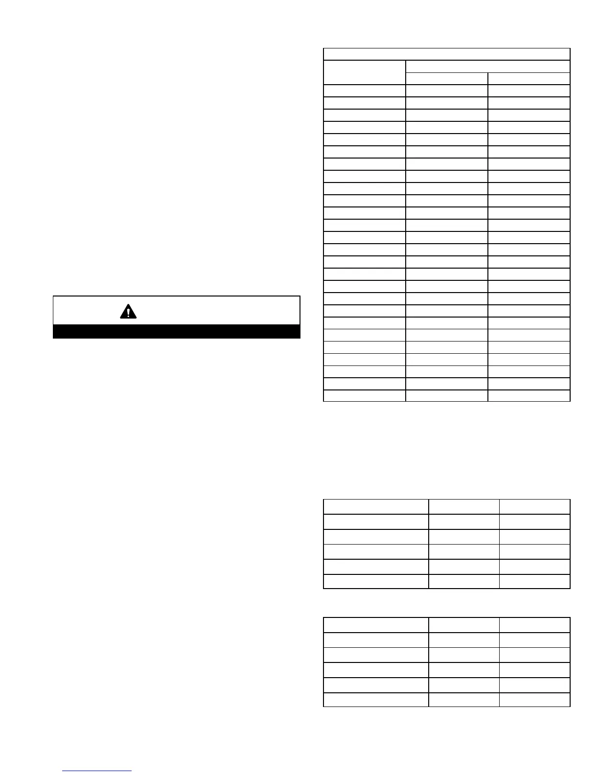
2 − Compare the number of seconds and the gas meter
size in table 39 to determine the gas flow rate. Multiply
the gas flow rate by the heating value to determine the
unit input rate. If manifold pressure is correct and the
unit input rate is incorrect, check gas orifices for proper
size and restriction.
3 − Remove temporary gas meter if installed.
NOTE − To obtain accurate reading, shut off all other gas
appliances connected to meter.
TABLE 39
Gas Flow Rate (Ft.
3
/Hr.)
Seconds for 1
Revolution
Gas Meter Size
1/2 cu ft Dial 1 cu ft Dial
10 180 360
12 150 300
14 129 257
16 113 225
18 100 200
20 90 180
22 82 164
24 75 150
26 69 138
28 64 129
30 60 120
32 56 113
34 53 106
36 50 100
38 47 95
40 45 90
42 43 86
44 41 82
46 39 78
48 38 75
50 36 72
52 35 69
54 33 67
56 32 64
58 31 62
60 30 60
G− Proper Combustion
Furnace should operate minimum 15 minutes with correct
manifold pressure and gas flow rate before checking com-
bustion. Take combustion sample beyond the flue outlet
and compare to the tables below. The maximum carbon
monoxide reading should not exceed 100 ppm.
TABLE 40
High Fire
Unit
CO
2
%
For
Nat
CO
2
%
For
L.P.
G71MPP−36B−070 6.8 − 7.8 8.5 − 9.5
G71MPP−36C−090 7.2 − 8.2 8.5 − 9.5
G71MPP−60C−090 7.2 − 8.2 7.2 − 8.2
G71MPP−60C−110 7.6 − 8.6 7.6 − 8.6
G71MPP−60D−135 7.5 − 8.5 7.5 − 8.5
TABLE 41
Low Fire
Unit CO
2
%
For
Nat
CO
2
%
For
L.P.
G71MPP−36B−070 5.0 − 6.0 5.8 − 6.8
G71MPP−36C−090 4.9 − 5.9 5.7 − 6.7
G71MPP−60C−090 4.9 − 5.9 5.7 − 6.7
G71MPP−60C−110 5.0 − 6.0 6.2 − 7.2
G71MPP−60D−135 5.0 − 6.0 5.7 − 6.7
 Loading...