Page 7
TABLE 4
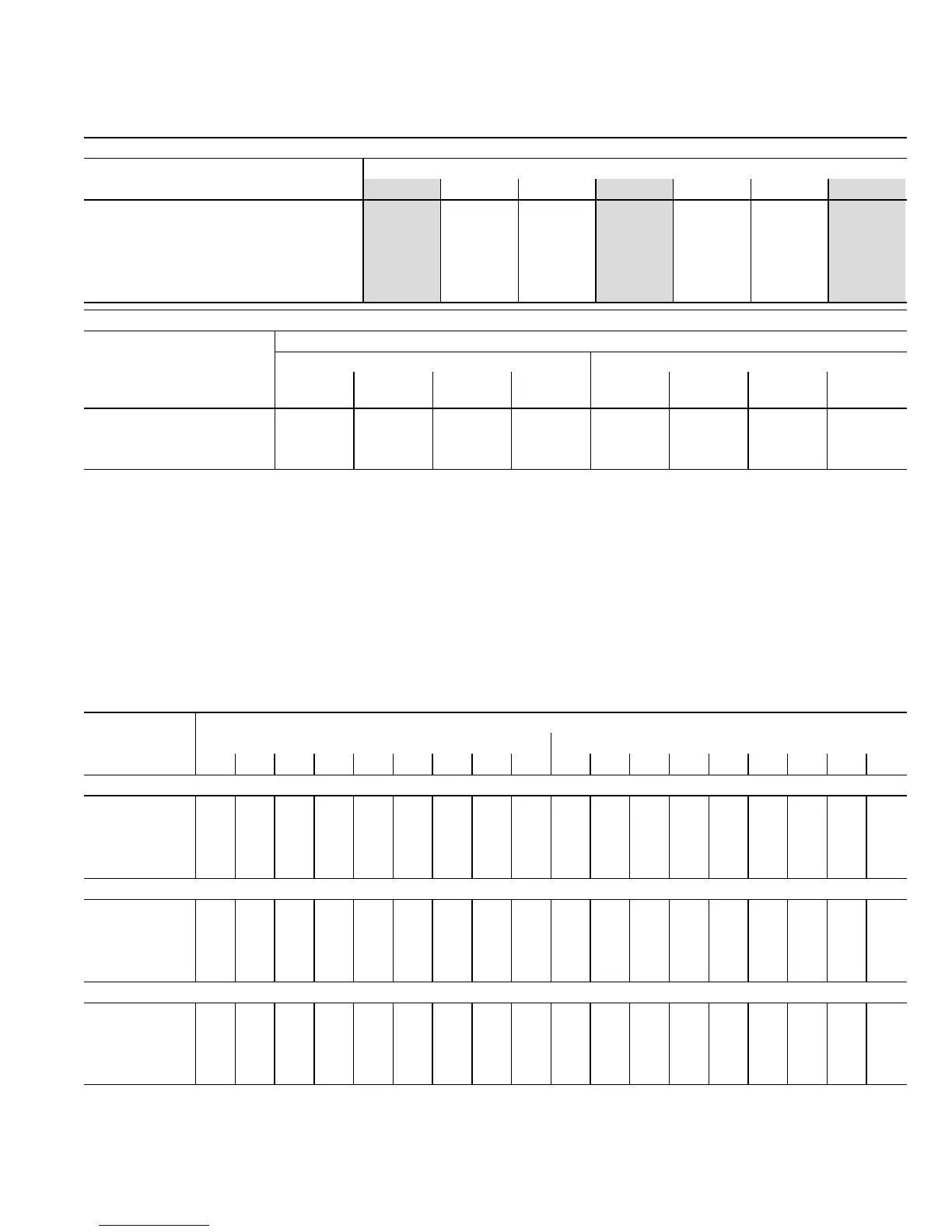
G71MPP−60C−090 BLOWER PERFORMANCE (less filter) −− Single Side Return Air
(Air volumes in bold require field fabricated transition to accommodate 20 x 25 x 1 in. cleanable air filter
in order to maintain proper air velocity across the filter.)
0 through 0.80 in. w.g. External Static Pressure Range
HEATING BLOWER PERFORMANCE
Heating Adjust CFM Selections
Heating Input Range and Blower Volume − CFM
40% 50% 60% 70% 80% 90% 100%
Increase (+15%) Heat CFM 655 790 920 1050 1180 1310 1440
Increase (+7.5%) Heat CFM 605 725 850 970 1090 1205 1325
Default Heat CFM 555 675 790 905 1015 1125 1235
Decrease (–7.5% ) Heat CFM 515 625 730 835 940 1045 1150
Decrease (–15% ) Heat CFM 465 565 665 765 860 960 1055
COOLING BLOWER PERFORMANCE
Cooling Adjust CFM
Selections
Blower Speed Selections
First Stage Cool Speed − cfm Second Stage Cool Speed − cfm
Low
Medium−
Low
Medium
High
High
(Default)
Low
Medium−
Low
Medium
High
High
(Default)
Increase (+10%) Cool CFM 1080 1160 1315 1490 1575 1690 1895 2135
Default Cool CFM 985 1060 1185 1330 1405 1530 1735 1935
Decrease (–10%) Cool CFM 865 930 1065 1185 1250 1355 1560 1735
The effect of static pressure is included in air volumes shown.
Lennox Harmony IIIt Zone Control Applications − Minimum blower speed is 450 cfm.
The following control board configurations are available. See Installation Instructions for details and DIP switch settings.
Heat Mode (Heating Blower Performance Table):
With a single−stage thermostat, furnace will operate at three, staged rates (40/70/100%) with a time delay between each stage (values in grey−shaded
columns).
With two−stage thermostat there are two modes available.
Traditional two−stage mode − W1 demand results in 70% firing rate. W2 results in 100% firing rate. No delay between stages. (values shown in 70%
and 100% grey−shaded columns only).
Variable Rate Capacity Mode − furnace automatically adjusts firing rate based on first− and second−stage cycle times. (all columns)
Cool Mode (Cooling Blower Performance table):
First stage COOL (two−stage air conditioning units only) is approximately 70% of the same second stage COOL speed position.
Continuous Fan speeds are approximately 28%, 38%, 70% and 100% (DIP switch selectable) of the same second−stage COOL speed position
minimum 450 cfm.
G71MPP−60C−090 BLOWER MOTOR WATTS − COOLING
Blower Speed
Options
Motor Watts @ Various External Static Pressures − in. wg.
First Stage Second Stage
0 0.10 0.20 0.30 0.40 0.50 0.60 0.70 0.80 0 0.10 0.20 0.30 0.40 0.50 0.60 0.70 0.80
Increase (+10%) Cool CFM
Low 110 130 155 180 205 225 245 270 290 285 320 355 390 430 465 500 535 565
Medium−Low 125 150 175 205 225 250 275 300 325 355 390 430 470 500 530 570 605 645
Medium−High 170 195 230 260 290 325 355 385 415 515 550 590 625 670 710 750 795 840
High 240 275 315 355 380 405 445 485 525 740 785 835 885 920 955 990 1020 1050
Default Cool CFM
Low 85 100 125 145 170 200 215 235 255 200 230 270 310 340 370 400 430 460
Medium−Low 105 125 150 170 195 220 240 260 280 260 295 330 365 400 440 470 500 530
Medium−High 135 160 185 215 240 270 290 315 335 410 440 470 500 540 580 610 640 670
High 170 200 235 265 305 340 365 390 415 550 585 620 655 695 740 780 825 865
Decrease (–10%) Cool CFM
Low 65 80 100 120 140 160 180 205 225 180 215 245 265 290 320 345 375 445
Medium−Low 75 90 110 130 155 180 200 220 245 220 250 275 305 335 370 400 430 510
Medium−High 100 120 150 175 200 220 245 265 290 320 350 385 415 445 485 520 560 635
High 135 160 185 215 240 265 290 315 335 435 465 495 540 585 610 640 665 765