Page 9
New or Replacement Line Set
This section provides information on new installation or re-
placement of existing line set. If a new or replacement line
set is not required, then proceed to Brazing Connections
on page 11.
If refrigerant lines are routed through a wall, seal and
isolate the opening so vibration is not transmitted to the
building. Pay close attention to line set isolation during
installation of any HVAC system. When properly isolated
from building structures (walls, ceilings. oors), the refrig-
erant lines will not create unnecessary vibration and sub-
sequent sounds.
REFRIGERANT LINE SET
Field refrigerant piping consists of liquid and suction lines
from the outdoor unit (braze connections) to the indoor
unit coil (are or braze connections). Use Lennox L15
(braze, non-are) series line set, or use eld-fabricated
refrigerant lines as listed in table 2.
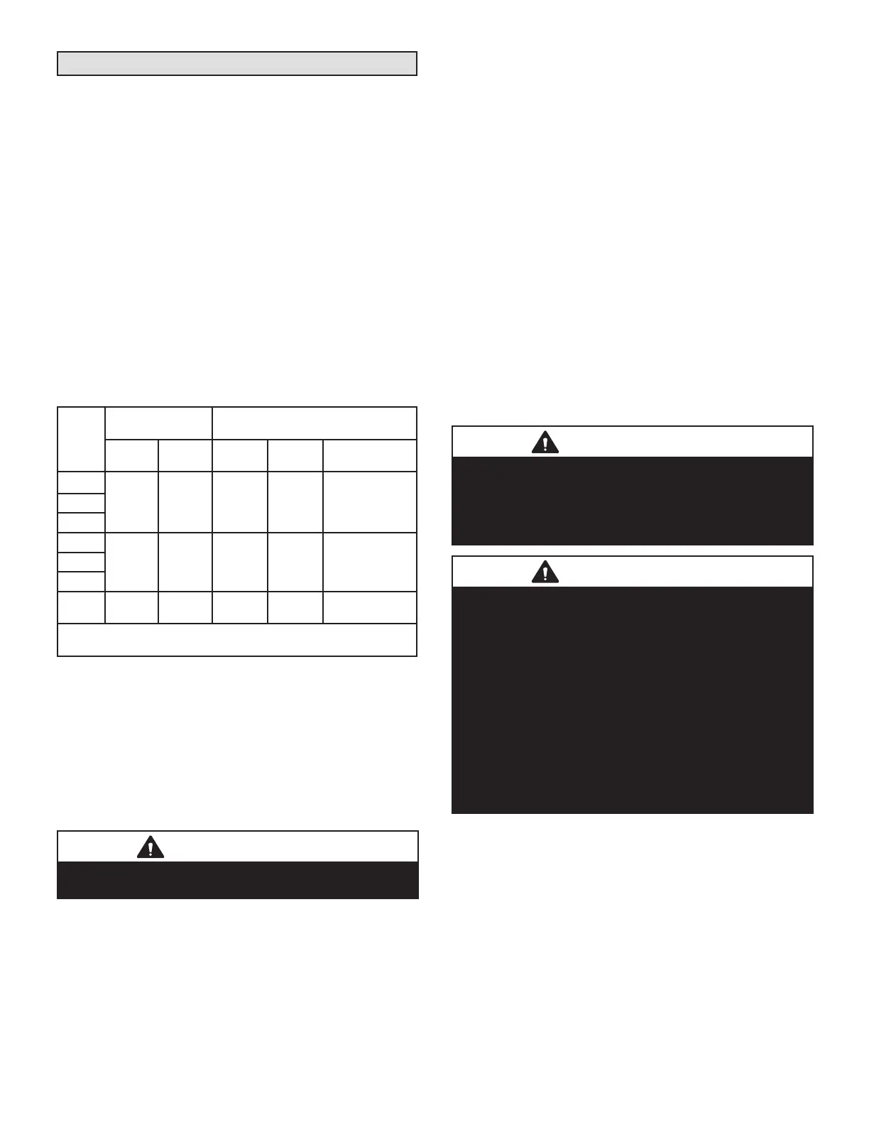
TABLE 2. Refrigerant Line Set – in. (mm)
Model
Valve Field
Connections
Recommended Line Set
Liquid
Line
Vapor
Line
Liquid
Line
Vapor
Line
L15 Line Sets
-018
3/8 in.
(10 mm)
3/4 in.
(19 mm)
3/8 in.
(10 mm)
3/4 in.
(19 mm)
L15-41
15 ft. - 50 ft.
(4.6 m - 15 m)
-024
-030
-036
3/8 in.
(10 mm)
7/8 in.
(22 mm)
3/8 in.
(10 mm)
7/8 in.
(22 mm)
L15-65
15 ft. - 50 ft.
(4.6 m - 15 m)
-042
-048
-060
3/8 in.
(10 mm)
1-1/8 in.
(28 mm)
3/8 in.
(10 mm)
1-1/8 in.
(28 mm)
Field Fabricated
NOTE - Some applications may require a eld-provided 7/8" to
1-1/8" adapter.
NOTE – When installing refrigerant lines longer than 50
feet, contact Lennox Technical Support Product Applica-
tions for assistance or Lennox piping manual. To obtain
the correct information from Lennox, be sure to communi-
cate the following points:
• Model (EL16XP1) and size of unit (e.g. -060).
• Line set diameters for the unit being installed as listed in
table 4 and total length of installation.
• Number of elbows and if there is a rise or drop of the piping.
IMPORTANT
Mineral oils are not compatible with HFC-410A. If oil
must be added, it must be a Polyol ester oil.
The compressor is charged with sucient Polyol ester oil
for line set lengths up to 50 feet. Recommend adding oil to
system based on the amount of refrigerant charge in the
system. No need to add oil in system with 20 pounds of
refrigerant or less. For systems over 20 pounds - add one
ounce for every ve pounds of refrigerant.
Recommended topping-o POE oils are Mobil EAL ARC-
TIC 22 CC or ICI EMKARATE RL32CF.
MATCHING WITH NEW OR EXISTING INDOOR COIL
AND LINE SET
The RFC1-metering line consisted of a small bore copper
line that ran from condenser to evaporator coil. Refrig-
erant was metered into the evaporator by utilizing tem-
perature/pressure evaporation eects on refrigerant in the
small RFC line. The length and bore of the RFC line cor-
responded to the size of cooling unit. If the EL16XP1 is
being used with either a new or existing indoor coil which
is equipped with a liquid line which served as a meter-
ing device (RFCI), the liquid line must be replaced prior to
the installation of the EL16XP1 unit. Typically a liquid line
used to meter ow is 1/4” in diameter and copper.
LINE SET INSTALLATION AND ISOLATION
IMPORTANT
The Clean Air Act of 1990 bans the intentional venting
of refrigerant (CFC’s and HCFC’s) as of July 1, 1992.
Approved methods of recovery, recycling or reclaiming
must be followed. Fines and/or incarceration may be
levied for non-compliance.
IMPORTANT
If this unit is being matched with an approved line set
or indoor unit coil that was previously charged with
mineral oil, or if it is being matched with a coil which
was manufactured before January of 1999, the coil and
line set must be ushed prior to installation. Take care to
empty all existing traps. Polyol ester (POE) oils are used
in Lennox units charged with HFC-410A refrigerant.
Residual mineral oil can act as an insulator, preventing
proper heat transfer. It can also clog the expansion
device and reduce system performance and capacity.
Failure to properly ush the system, per this instruction
and the detailed Installation and Service Procedures
manual will void the warranty.
 Loading...
