Do you have a question about the Lennox HP29-024 and is the answer not in the manual?
| Cooling Capacity (BTU) | 24000 |
|---|---|
| Refrigerant Type | R-410A |
| Number of Stages | 1 |
| Voltage (V) | 208/230 |
| Phase | 1 |
| Unit Weight (lbs) | 220 |
Detailed technical specifications for various HP29 models.
Electrical parameters for different HP29 models, including amps and power factor.
Details on the electrical control box and thermostat wiring identification.
Illustration of major unit components like compressor and control box.
Description and function of the step-down transformer T5.
Explanation of dual capacitors for single-phase motors.
Role of the potential relay in starting single-phase reciprocating compressors.
Function and rating of the start capacitor for reciprocating compressors.
Capacitor rating for fan motors in three-phase units.
Relay for energizing the outdoor fan motor.
Contactor for energizing the compressor.
Operation and settings of the defrost thermostat.
Functions of the defrost control board, including timing and diagnostics.
Explanation of timing pin selections for defrost cycle initiation.
How pressure switches interact with the defrost control safety circuit.
Interpretation of diagnostic LEDs for troubleshooting defrost control issues.
Operation of the defrost thermostat for newer units.
Functions of the defrost control board in newer systems.
Timing adjustments for the defrost cycle in newer units.
Pressure switch integration for optional units.
LED indicators for troubleshooting optional units.
Function of the 5-minute time delay feature.
Connections for ambient thermistor and service light.
Specifications for reciprocating compressors used in HP29 units.
Specifications for scroll compressors used in HP29 units.
Procedures for ensuring correct three-phase compressor phasing.
Description of the compressor cover's construction and purpose.
Function and ratings of the crankcase heater for reciprocating compressors.
Access and specifications for the condenser fan motor.
Function of the reversing valve for refrigerant flow control.
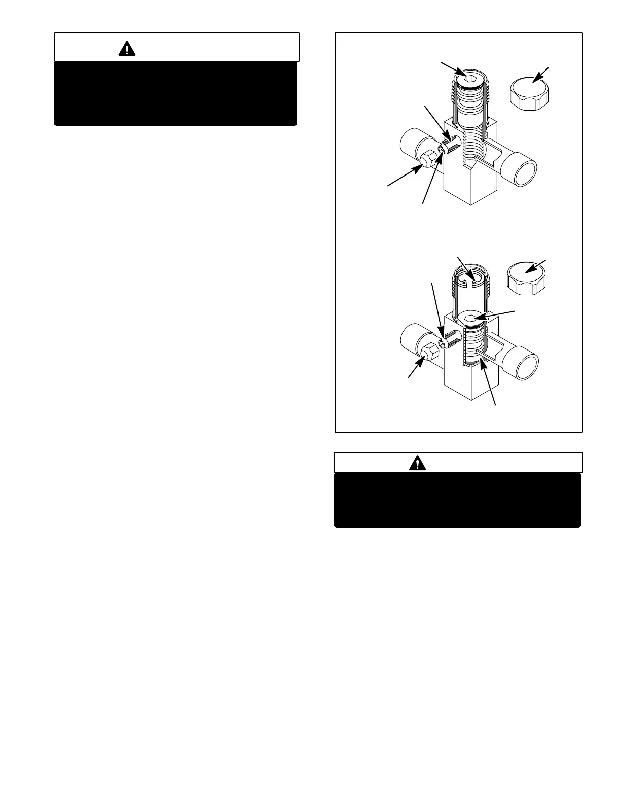
Description and accessibility of service valves for refrigerant handling.
Procedures for opening and closing liquid line service valves.
Procedures for opening and closing vapor line service valves.
Specifics on ball-type service valves for 5-ton units.
Table showing line set lengths, liquid and vapor line diameters for models.
Diagram of outdoor unit refrigerant components.
Procedure for pumping down the system before leak checking.
Steps for leak testing the system before evacuation.
Procedures for evacuating the refrigerant system to a specific vacuum level.
Charging procedure for ambient temperatures 60°F or above.
Charging procedure for ambient temperatures below 60°F.
Typical operating pressures for cooling and heating modes.
Procedures for installing line sets on vertical runs to prevent noise.
Procedures for installing line sets on horizontal runs to prevent noise.
Method for transitioning line sets between vertical and horizontal runs.
Guidelines for placing the outdoor unit and line set.
Wiring diagram for single-phase units with reciprocating compressors.
Detailed wiring diagram for HP29 single-phase reciprocating compressor units.
Detailed wiring diagram for HP29 single-phase reciprocating compressor units.
Wiring diagram for single-phase units with scroll compressors.
Detailed wiring diagram for HP29 single-phase scroll compressor units.
Detailed wiring diagram for HP29 single-phase scroll compressor units.
Sequence of operation for HP29 'P' voltage units, covering cooling, heating, and defrost.
Wiring diagram for three-phase HP29 units with reciprocating or scroll compressors.
Wiring diagram for three-phase HP29 units with reciprocating or scroll compressors.
Sequence of operation for three-phase HP29 units, covering cooling, heating, and defrost.

