Page 10
Defrost Control CMC1
The defrost control board combines functions of a time /
temperature initiated and time / pressure terminated defrost
control, defrost relay, time delay, diagnostic LEDs and field
connection terminal strip. See figure 10.
The control provides automatic switching from normal
heating operation to defrost mode and back. During com
pressor cycle (call for defrost), the control accumulates
compressor run times at 30, 60 or 90 minute field adjust
able intervals. If the defrost thermostat remains closed
when the accumulated compressor run time ends, the de
frost relay is energized and defrost begins. The defrost
cycle is terminated by the defrost pressure switch or in 14
minutes whichever occurs first.
Defrost Control Components
1− Defrost Control Timing Pins
Each timing pin selection provides a different accumu
lated compressor run period during one thermostat run
cycle. This time period must occur before a defrost cycle
is initiated. The defrost interval can be adjusted to 30, 60
or 90 minutes. See figure 10. If no timing is selected, the
control defaults to the factory setting 90 minutes. The de
frost period is a maximum of 14 minutes and cannot be
adjusted.
A TEST option is provided for troubleshooting. When the
jumper is placed across the TEST pins, the timing of all
functions is reduced by a factor of 128. For example, a 90
minute interval during TEST is 42 seconds and the 14−min
ute defrost is reduced to 6.5 seconds.
The TEST mode may be started at anytime. If the jumper is
in the TEST position at power−up or for longer than five min
utes, the control will ignore the TEST selection and will de
fault to a 90 minute interval. In order to test defrost cycle,
defrost thermostat must be closed or jumpered. Once
defrost is initiated, remove jumper immediately. Failure to
remove jumper will reduce defrost time to seconds.
2− Time Delay
The timed−off delay is five minutes long. The delay feature
is provided to help protect the compressor in case of inter
ruption in power to the unit before thermostat demand is
satisfied, or when a pressure switch resets. If thermostat
demand is satisfied and the off cycle is greater than 5 min
utes, the compressor will energize immediately on next
heating or cooling demand.
3− Pressure Switch Safety Circuits
The defrost control incorporates a pressure switch safety
circuit that allows the application of an additional pressure
switch; high pressure switch (S4) is factory−wired to this cir
cuit. See figure 10. PS1 and PS2 terminals are internally
connected in series with a jumper internal to the control
board.
During one demand cycle, the defrost control will lock out
the unit on the third instance that the unit goes off on any
auto−reset pressure switch wired to this circuit. The diag
nostic LEDs will display a pattern for a locked out pressure
switch on the third open pressure switch occurrence. See
table 1. The unit will remain locked out until power is bro
ken then remade to the control.
The PS2 safety circuit terminals are connected to the com
pressor thermostat.
4− Diagnostic LEDs
The defrost board uses two LEDs for diagnostics. The
LEDs flash a specific sequence according to the condi
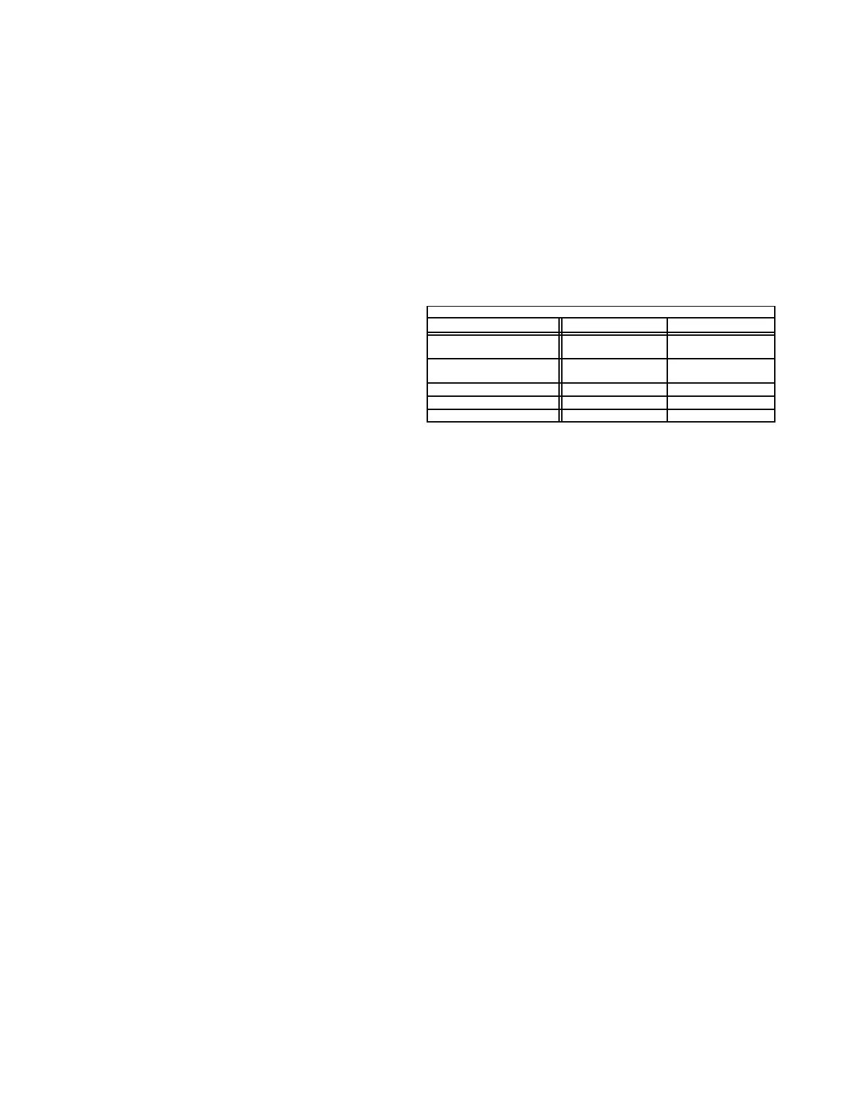
tion. See table 1.
TABLE 1
DEFROST CONTROL BOARD DIAGNOSTIC LED
MODE LED 1 LED 2
Normal Operation/
Power to board
Flash together with
LED 2
Flash together with
LED 1
Time Delay
To Protect Compressor
Alternating Flashes
with LED 2
Alternating Flashes
with LED 1
Pressure Switch Open Off On
Pressure Switch Lockout On Off
Board Malfunction On On
5−Anti−Short Cycle
This feature of the board prevents the compressor from be
ing short−cycled which could result in damage. An internal
board timer prevents the compressor from being ener
gized for approximately 5 minutes, after thermostat de
mand is met. During this time off, the system refrigerant
pressure is able to equalize (between low and high sides)
which eases compressor start up.
6−Ambient (outdoor air) Thermistor
The defrost control board has two terminal connections for
an ambient thermistor. The thermistor compensates for
changes in the outdoor air temperature. This change in
temperature can cause thermostat droop. Droop may be
defined as the difference between the room thermostat
set−point and the lowest temperature of the indoor air once
the indoor blower is energized. Cool air (relative to thermo
stat set−point or desired room air temperature) will enter
the home when the indoor blower is energized. The therm
istor raises the thermostat set−point by a fractional amount
(1 or 2° F) to keep the indoor air temperature near the ther
mostat set−point.
7−Service Light Connection
Terminal connections W1, L and C are for the addition of a
thermostat service light. This light can be used with any
thermostat. It is powered from the W1 (second stage heat)
terminal of the indoor thermostat and is controlled by a dis
charge line thermostat (S54). The discharge line thermo
stat will close and activate the service light when discharge
line temperature drops below 110°F 5° during compres
sor operation. The light informs the home owner of a prob
lem with the system (specifically the compressor). When
the light is on, second stage heating may be initiated. The
normally closed thermostat will open when discharge line
reaches 130°F 5° which requires 30 to 40 seconds of
compressor operation, at which time the service light is de−
energized.
 Loading...
