Page 13
II− REFRIGERANT SYSTEM
A−Plumbing
Field refrigerant piping consists of liquid and vapor lines
from the outdoor unit (sweat connections) to the indoor
evaporator coil (sweat connections). Refer to table 2 for
field−fabricated refrigerant line sizes. Refer to Lennox Re
frigerant Piping manual Corp. #9351−L9 for proper size,
type and application of field−fabricated lines. Separate dis
charge and suction service ports are provided at the com
pressor for connection of gauge manifold during charging
procedure.
B−Accumulator
All HP29−2 units are equipped with an accumulator. The
accumulator prevents compressor slugging by holding ex
cess refrigerant and then slowly metering it back into the
system.
TABLE 2
REFRIGERANT LINE SIZES
HP29
UNIT
LIQUID
LINE
VAPOR
LINE
090
5/8 in
(16 mm)
1−3/8 in
(35mm)
120 5/8 in
(16 mm)
1−3/8 in
(35mm)
C−Service Valves
All HP29 units are equipped with service valves located in
the liquid and vapor lines. The service valves are manually
operated. See figures 14 and 15. The service ports are
used for leak testing, evacuating, charging and checking
charge.
1 − Liquid Line Service Valve
A fullservice liquid line valve made by one of several
manufacturers may be used. All liquid line service valves
function the same way, differences are in construction.
Valves are not rebuildable. If a valve has failed, it must be
replaced. The liquid line service valve is illustrated in figure
14.
A schrader valve is factory installed. A service port cap is
supplied to protect the schrader valve from contamination
and to serve as primary leak seal.
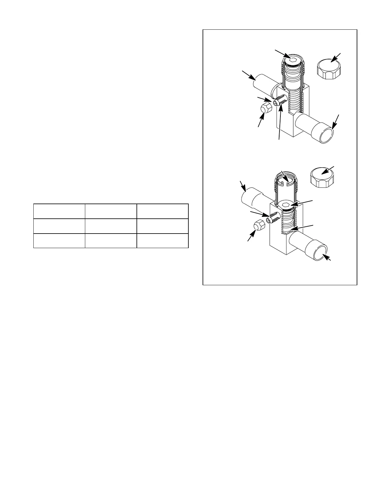
FIGURE 14
LIQUID LINE SERVICE VALVE (VALVE OPEN)
VALVE
CORE
SERVICE PORT
SERVICE PORT
CAP
INSERT HEX
WRENCH HERE
INLET (TO
INDOOR COIL)
OUTLET (TO
COMPRESSOR)
STEM CAP
VALVE CORE OPEN
TO LINE SET WHEN VALVE IS
CLOSED (FRONT SEATED)
SERVICE
PORT
SERVICE PORT
CAP
RETAINING RING
(−2 units only)
STEM CAP
INSERT HEX
WRENCH HERE
LIQUID LINE SERVICE VALVE (VALVE CLOSED)
(VALVE FRONT
SEATED)
INLET (TO
INDOOR COIL)
OUTLET (TO
COMPRESSOR)
To Access Service Port:
1 − Remove service port cap with an adjustable wrench.
2 − Connect gauge to the service port.
3 − When testing is completed, replace service port cap.
Tighten finger tight, then an additional 1/6 turn. Do not
over−torque.
Open Liquid Line Service Valve:
1 − Remove stem cap with an adjustable wrench.
2 − Using service wrench and 5/16" hex head extension (part
#49A71) back the stem out counterclockwise until the
valve stem just touches the retaining ring. Make sure
wrench fits properly to avoid stripping stem.
3 − Replace stem cap. Tighten finger tight, then tighten an
additional 1/6 turn.
 Loading...
