Page 16
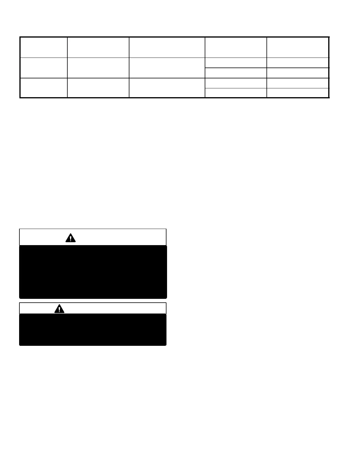
TABLE 3
UNIT MODEL
NUMBER
MATCHED
INDOOR UNIT
HCFC22 FOR 25 FEET
(7.6 m) OF LINE
LIQUID LINE
DIAMETER
ADJUSTMENT PER
FOOT (.3 m) OF LINE*
HP29−090−2
23 lbs.
10.4 k
5/8 in. (16 mm) 1.8 oz.. (51g)
HP29−090−3
17
17−95
.
.
21.5 lbs. (9.8 kg)
3/4 in. (19 mm) 2.6 oz.. (74g)
HP29−120−2
31 lbs.
14.1 k
5/8 in. (16 mm) 1.8 oz.. (51g)
HP29−120−3
17
17−135
.
.
30 lbs. (13.6 kg)
3/4 in. (19 mm) 2.6 oz.. (74g)
* If line length is greater than 25 feet (7.62 m), add this amount. If line length is less than 25 feet (7.62 m), subtract this amount.
NOTE − Refrigerant line sets should not be longer than 100 feet (30.5 m). Refrigerant line losses deduct from the net capac
ity of the system. Additional refrigerant required for such systems may also upset the refrigeranttooil ratio.
B−Evacuating the System
Evacuating the system of non−condensables is critical for
proper operation of the unit. Non−condensables are defined
as any gas that will not condense under temperatures and
pressures present during operation of an air conditioning
system. Non−condensable such as water vapor, nitrogen,
helium and air combines with refrigerant to produce sub
stances that corrode copper piping and compressor parts.
1 − Connect manifold gauge set to the service valve ports
as follows: low pressure gauge to vapor line service
valve; high pressure gauge to liquid line service valve.
CAUTION
Danger of Equipment Damage.
Avoid deep vacuum operation. Do not use com
pressors to evacuate a system.
Extremely low vacuums can cause internal arcing
and compressor failure.
Damage caused by deep vacuum operation will
void warranty.
IMPORTANT
A temperature vacuum gauge, mercury vacuum
(U−tube), or thermocouple gauge should be used.
The usual Bourdon tube gauges are not accurate
enough in the vacuum range.
2 − Connect the vacuum pump (with vacuum gauge) to
the center port of the manifold gauge set.
3 − Open both manifold valves and start vacuum pump.
4 − Evacuate the line set, indoor unit and outdoor unit to an
absolute pressure of 23mm of mercury or approxi
mately 1 inch of mercury. During the early stages of
evacuation, it is desirable to close the manifold gauge
valve at least once to determine if there is a rapid rise in
absolute pressure. A rapid rise in pressure indicates
a relatively large leak. If this occurs, the leak testing
procedure must be repeated after the leak is repaired.
NOTE − The term absolute pressure means the total
actual pressure within a given volume or system,
above the absolute zero of pressure. Absolute pres
sure in a vacuum is equal to atmospheric pressure mi
nus vacuum pressure.
5 − When the absolute pressure reaches 23mm of mercu
ry, close the manifold gauge valves, turn off the vacu
um pump and disconnect the manifold gauge center
port hose from vacuum pump. Attach the manifold
center port hose to a nitrogen cylinder with pressure
regulator set to 150 psig (1034 kPa) and purge the
hose. Open the manifold gauge valves to break the
vacuum in the line set and indoor unit. Close the man
ifold gauge valves.
6 − Shut off the nitrogen cylinder and remove the manifold
gauge hose from the cylinder. Open the manifold
gauge valves to release the nitrogen from the line set
and indoor unit.
7 − Reconnect the manifold gauge to the vacuum pump,
turn the pump on and continue to evacuate the line set,
indoor unit and outdoor until the absolute pressure
does not rise above .5mm of mercury within a 20 min
ute period after shutting off the vacuum pump and
closing the manifold gauge valves.
8 − Depending on the equipment used to determine the
vacuum level, absolute pressure of .5mm of mercury is
equal to 500 microns.
9− When the absolute pressure requirement above has
been met, disconnect the manifold hose from the vacu
um pump and connect it to an upright bottle of HCFC22
refrigerant. Open the manifold gauge valves to break
the vacuum in the line set and indoor unit. Close man
ifold gauge valves and shut off HCFC22 bottle and re
move manifold gauge set.
 Loading...
