Page 8
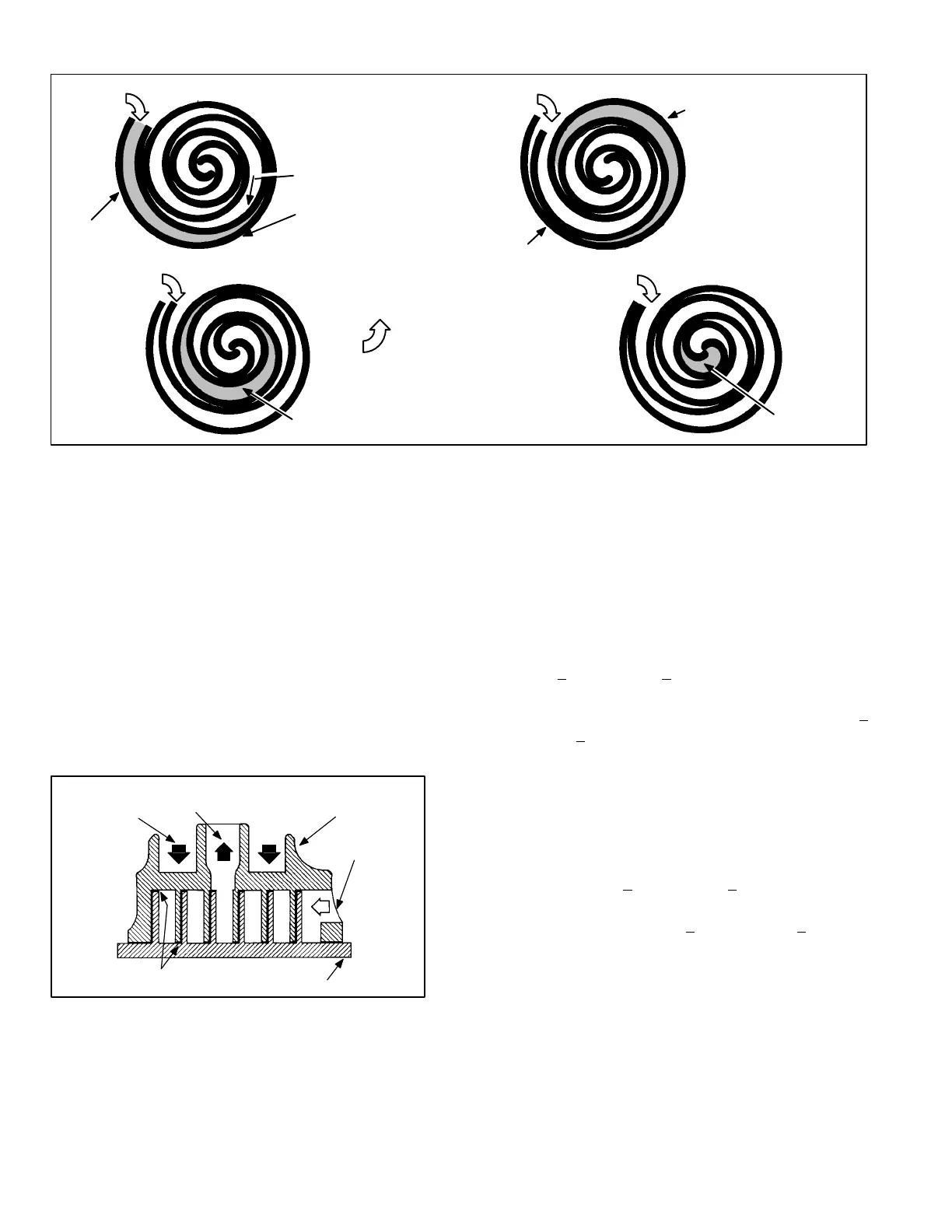
FIGURE 8
1
2
3
4
SUCTION
POCKET
SUCTION
ORBITING SCROLL
STATIONARY SCROLL
SUCTION
SUCTION
DISCHARGE
POCKET
SUCTION
INTERMEDIATE PRESSURE
GAS
CRECENT SHAPED
GAS POCKET
HIGH PRESURE GAS
FLANKS SEALED
BY CENTRIFIGUAL
FORCE
MOVEMENT OF ORBIT
The counterclockwise orbiting scroll draws gas into the
outer crescent shaped gas pocket created by the two
scrolls (figure 8−2). The centrifugal action of the orbiting
scroll seals off the flanks of the scrolls (figure 8−3). As the
orbiting motion continues, the gas is forced toward the cen
ter of the scroll and the gas pocket becomes compressed
(figure 8−4).
When compressed gas reaches the center, it is discharged
vertically into a chamber and discharge port in the top of
the compressor (figure 6). The discharge pressure forcing
down on the top scroll helps seal the upper and lower
edges (tips) of the scrolls (figure 9). During a single orbit,
several pockets of gas are compressed simultaneously
providing smooth continuous compression.
STATIONARY SCROLL
ORBITING SCROLL
DISCHARGE
SUCTION
CROSS−SECTION OF SCROLLS
TIPS SEALED BY
DISCHARGE PRESSURE
DISCHARGE
PRESSURE
FIGURE 9
2 − Crankcase Heaters HR1 (all units)
All HP29 units use a belly−band crankcase heater. Heater
HR1 is wrapped around compressor B1. HR1 assures
proper compressor lubrication at all times.
3 − High Pressure Switch S4 (all units)
The high pressure switch is a manual−reset SPST N.C.
switch which opens on a pressure rise. The switch is lo
cated on the compressor discharge line and is wired to the
defrost control board CMC1. When discharge pressure
rises to 450 + 10 psig (3103 + 69 kPa) the switch opens and
the compressor is de−energized through the CMC1. The
switch will close when discharge pressure drops to 300 +
20 psig (2068 + 138 kPA).
4 − Low Ambient Switch S11 (all units)
The low ambient switch is an auto−reset SPST N.O. pres
sure switch, which allows for mechanical cooling operation
at low outdoor temperatures. All HP29 units are equipped
with S11. The switch is located in the liquid line. In all HP29
units, S11 is wired in series with fan relay K10. When liquid
pressure rises to 275 + 10 psig (1896 + 69 kPa), the switch
closes and the condenser fan is energized. When the dis
charge pressure drops to 150 + 10 psig (1034 + 69 kPa),
the switch opens and the condenser fan is de−energized.
This intermittent fan operation results in higher evaporat
ing temperature, allowing the system to operate without ic
ing the evaporator coil and losing capacity.
 Loading...
