Page 7
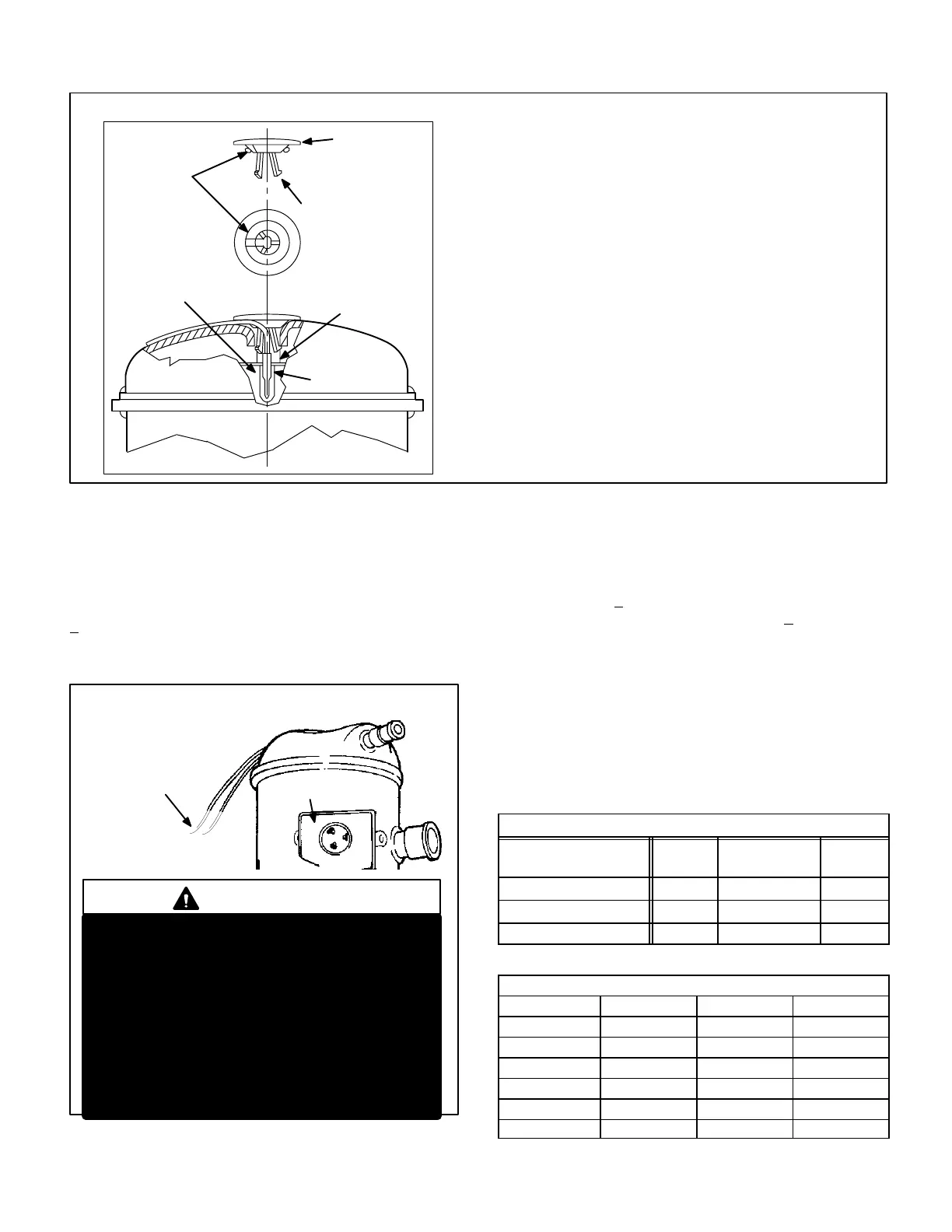
FIGURE 7
COMPRESSOR HIGH TEMPERATURE LIMIT CHANGEOUT (EARLY MODELS ONLY)
Instructions
1 With power off, disconnect wiring to limit.
2 Dislodge limit/cap assembly from compressor. Plastic cap and silicone seal
will break away. Discard all pieces.
3 Remove thermostat and grommet from compressor. Thoroughly clean all
blue adhesive and white silicone thermal grease from compressor and the
inside of the thermostat tube. Thermostat tube should be clean and free of
debris.
4 Using Lennox kit 93G8601, dip end of thermostat into plastic bottle labeled
Silicone Thermal Grease G.E. #G641" and coat end of thermostat. Care
fully insert thermostat/grommet assembly into thermostat tube of compres
sor. Avoid contact with top of compressor.
5 Clean excess thermal grease from under cap lip and top lip of compressor
opening.
6 Install protector assembly as shown, feeding wire leads through channel
provided in cap.
7 Apply a bead of sealant around lip of cap at area shown in illustration and
into the thermostat tube area.
8 Install assembly as shown. Align wires to channel in compressor shell. Suf
ficient force is required to snap plastic cap into tube to engage all three
prongs.
9 Reconnect wiring.
10After completing thermostat replacement, discard remaining parts.
PLASTIC CAP
PRONG
GROMMET
SEALANT
(BLUE)
COMPRESSOR
THERMAL
GREASE
(WHITE)
LIMIT
(THERMOSTAT)
G−High/Low Pressure Switch
A manualreset singlepole singlethrow high pressure switch
located in the liquid line, shuts off the compressor when liquid
line pressure rises above the factory setting. The switch is nor
mally closed and is permanently adjusted to trip (open) at 410
+ 10 psi. See figure 5 or 6 for switch location
COMPRESSOR TERMINAL BOX
C
S
R
COMPRESSOR
TERMINALS
FIGURE 8
WARNING
COMPRESSOR MUST BE GROUNDED. DO
NOT OPERATE WITHOUT PROTECTIVE COV
ER OVER TERMINALS. DISCONNECT ALL
POWER BEFORE REMOVING PROTECTIVE
COVER. DISCHARGE CAPACITORS BEFORE
SERVICING UNIT. COMPRESSOR WIRING DIA
GRAM IS FURNISHED INSIDE COMPRESSOR
TERMINAL BOX COVER. FAILURE TO FOL
LOW THESE PRECAUTIONS COULD CAUSE
ELECTRICAL SHOCK RESULTING IN INJURY
OR DEATH.
DISCHARGE TEMPERATURE
SENSOR WIRES
TO CONTROL BOX
(TO COMP. TERM. BOX IN
461 UNITS)
EARLY MODELS ONLY
An autoreset singlepole singlethrow low pressure switch
located in the suction line shuts off the compressor when
suction pressure drops below the factory setting. The
switch is normally closed and is permanently adjusted to
trip (open) at 25 + 5 psi. The switch automatically resets
when suction line pressure rises above 55 + 5 psi. See fig
ure 5 or 6 for switch location.
H−Dual Capacitor
The compressor and fan in HS26 single−phase units use
permanent split capacitor motors. A single dual" capacitor
is used for both the fan motor and the compressor (see unit
wiring diagram). The fan side of the capacitor and the com
pressor side of the capacitor have different mfd ratings. The
capacitor is located inside the unit control box (see figure 5
or 6). Tables 3 and 4 show the ratings of the dual capacitor.
TABLE 3 (Early Models)
HS26 DUAL CAPACITOR RATING
UNITS
FAN
MFD
HERM MFD VAC
HS26−261 5 30 370
HS26−311 5 35 370
HS26−411,−461 5 35 440
TABLE 4 (Late Models)
HS26 DUAL CAPACITOR RATING
UNITS FAN MFD HERM MFD VAC
HS26−018 4 30 370
HS26−024,−030 5 40 370
HS26−036 5 50 370
HS26−042 5 55 370
HS26−048 7.5 60 370
HS26−060 10 80 370
 Loading...