10
iComfort S30 Thermostat - Installer Zoning
Control Settings
Zoning Control Parameters
After completing the installation of the iHarmony Zoning
system. Power up the system. From the HD display, use the
following procedure to customize the zoning conguration.
1. From the Home screen, press the Menu icon in the
upper right-hand corner of the screen.
2. Press settings.
3. Press iHarmony zoning to rename each zone. Either
pre-dened or custom names can be used.
4. The rst line is zoning. Options are ON and OFF. By
default zoning is ON.
5. Select the specic zone to rename. Use the enter zone
name eld to rename the zone. Repeat to procedures
to rename any other zones if desired.
6. Once renaming zones is completed, press advanced
settings.
7. Press view dealer control center.
8. A warning message will appear indicating “intended
for use by qualied Lennox equipment installers only“.
Press proceed to continue.
9. Press equipment.
10. Press Zoning Control and modied any of the
available parameters for zoning control.
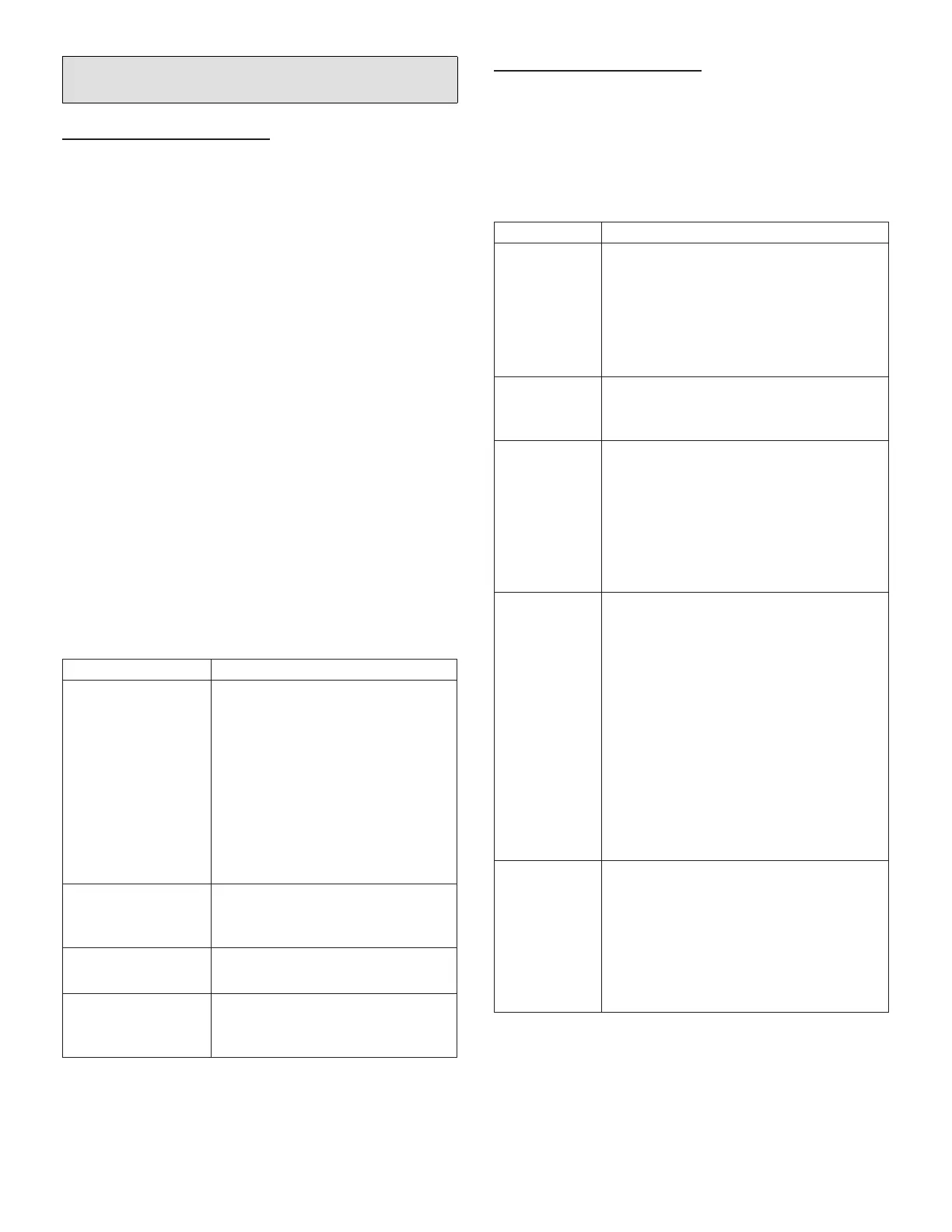
Table 10. Zoning Control Parameters
Parameter Description
About
This provides information on unit code,
language supported, equipment type
name, control software revision, control
model number, control serial number, con-
trol hardware revision, protocol revision
number, device product level, 24VAC av-
erage power consumption, 24VAC peak
power consumption, compatible devices
list, application code memory size, mi-
cro-controller part number, max number of
zones, supported damper types, number
of damper positions, zone temp sensor 1,
zone temp sensor 2, zone temp sensor 3
and zone temp sensor 4.
Equipment Name
A unique name can be assigned to this
component. Name can be up to 29 charac-
ters. Name can consist of letters, numbers,
special characters and spaces.
Zones 1 through
4 Temp Reading
Calibration
Allows adjustment to temperature reading
displayed on zone thermostat.
Reset Zoning
Control
Any installer modications under the zon-
ing control tab will be reset back to the
factory defaults if the reset zoning control
option is used.
Zoning System Parameters
1. From the dealer control center, press equipment.
2. Press smart hub.
3. Located and modied any setting related to zoning.
See below for list of parameters available for
modication.
Table 11. Smart Hub Parameters
Parameter Description
About
This screen provides information concerning lan-
guage supported, equipment type name, control
software revision, model, control mode number,
control serial number, control hardware revision,
protocol revision number, device product level,
24VAC average power consumption, 24VAC peak
power consumption, compatible devices list, appli-
cation code memory size and micro-controller part
number.
Equipment
Name
A unique name can be assigned to this compo-
nent. Name can be up to 29 characters. Name can
consist of letters, numbers, special characters and
spaces. Default name is subnet controller.
HP Heating
Lockout
Time
The HP could not get a zone to progress 0.5 de-
grees towards the set point in 120 minutes (Alert
Code 40 - Minor alert). System will switch to sec-
ondary heat source. (Electric heat or furnace in
dual fuel applications). Transition back to Heat
Pump normal operation when termination setting
times out.
Range is 60 to 240 minutes. Default is 120 min-
utes. Adjustments are in increments of 30 min-
utes.
Zone 1
through 4
Continuous
Blower
CFM
Minimum and maximum CFM will be dependent
on system component congurations. These pa-
rameter values are automatically adjusted to the
specic hardware conguration. See iHarmony
zoning system installation instruction for minimum
CFMs for specic indoor units.
Zones requesting the fan ON are only allowed
while no other zone demand is present. The ther-
mostat will sum all the zone continuous blower
CFM requirements and send the command only
after positioning the dampers and waiting for the
damper close delay period to expire (30 seconds)
Continuous blower demands are the lowest prior-
ity demands, all other conditioning demands will
over-ride the continuous blower demand.
Range is 5 CFM to maximum of indoor unit. De-
fault is dependent on tonnage of indoor unit. Ad-
justments are in increments of 5 CFM .
Zone 1
through
4 Cooling
CFM
Minimum and maximum CFM will be dependent
on system component congurations. These pa-
rameter values are automatically adjusted to the
specic hardware conguration. See iHarmony
zoning system installation instruction for minimum
CFMs for specic indoor units.
Target cooling CFM for a specic zone. Range is 5
CFM to maximum of indoor unit. Default is depen-
dent on tonnage of indoor unit. Adjustments are in
increments of 5 CFM.
 Loading...


