2
Required Items Sold Separately
The following items are also required for the zoning
system to operate:
1. In-zone thermostats (catalog number 10C17) — are
required for zones 2 through 4. Zone 1 is controlled
by the Lennox communicating thermostat. Works with
both iComfort Wi-Fi and S30 thermostats.
2. iHarmony Zone Sensor (17A30) which only works
with system controlled by an iComfort S30 thermostat.
3. Zone damper transformer, see “Table 1. Zone Damper
Transformer Selection Chart” for correct size.
4. Zone dampers — recommended zone dampers are
spring-open and power-close but you may also use
power-open and spring-close, or power-open and
power-close. Modulating dampers are not supported.
5. Optional freezestat, see “Table 4. Available
Freezestats” on page 5 for available freezestats
based on tubing sizes.
6. Fasteners to install the damper control module.
7. Heat Pump Applications Only: HFC-410A high
pressure switch (550PSI) (27W13) and valve
depressor tee (87071) are required.
IMPORTANT
Heat Pump Systems Only: Do not use jumper for
pressure switch terminals at the damper control module.
System will not function properly without pressure switch
installed.
Zone Damper Transformer
The zone dampers are powered by a eld−provided
24VAC transformer. Zone dampers require 6 to 12VA
each depending on zone damper used. The zone damper
transformer must have an adequate VA rating to serve all
components (see recommendations in following table).
The damper control module and three in- zone thermostats
require a total of 6VA to operate.
Table 1. Zone Damper Transformer Selection
Chart
Catalog
Number
Size Description VA LOAD =
10P17 40VA
120 / 208
240VAC,
24VAC
Damper VA x number
of dampers + 6VA
(damper control
module + 3 in -
-zone thermostats) =
damper transformer
VA requirement.
10P87 50VA
12P61 75VA
83P74 - Electrical Box (4-in. Square)
Recommended Items Sold Separately
Lennox recommends for furnace applications the use of air
bafes to help in mixing the supply air for better Discharge
Air Temperature Sensor accuracy.
Table 2. Recommended Air Bafes for Furnaces
Furnace Width Type Catalog Number
B 13X59
C 13X60
D 13X62
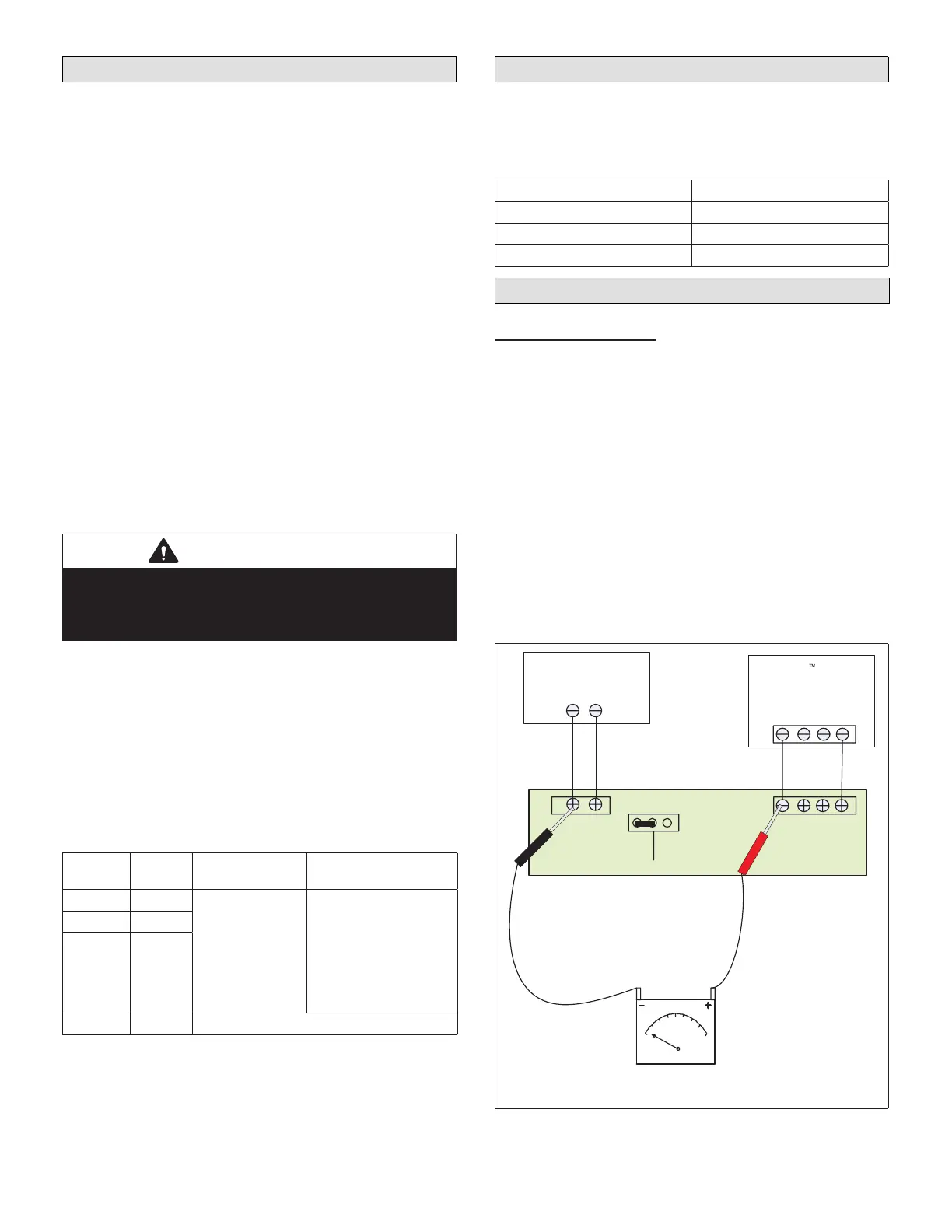
Zoning Components
Transformer Phasing
The indoor unit and zone damper transformers must be
in -phase since both are connected to the damper control
module. Follow the instructions below for phasing both
transformers.
1. Connect the damper control module indoor R and C to
the indoor unit R and C.
2. Connect the external 24VAC transformer to the damper
control module DMPR XFMR R and C terminals.
3. Measure voltage between the damper control module
indoor R and DPMR XFMR R terminals.
• In -phase voltage will be less than 10VAC.
• Out- of -phase voltage will be greater than 40VAC.
If voltage is greater than 40VAC, swap external
24VAC transformer (DMPR XFMR R and C) wires.
Ci−i+R
INDOOR
DMPR
XFMR
SYS
XFMR
iComfort -enabled
Furnace or Air
Handler
Ci−i+R
External 24VAC
Transformer
R
Damper Control
Module
Volt Meter
C
R
C
DMPRXFMR
Figure 1. Conrming Correct Transformer Phasing
(Polarity)
 Loading...


