5
• If the switch does not close within 60 seconds, the
Lennox communicating series thermostat stops heat
pump heating and satises the heating demand with
backup heat (backup heat is either electric or gas)
regardless of the ambient temperature being above the
hi balance point.
The heat pump is used again on the next call provided
the pressure switch has closed; otherwise backup heat
is used on subsequent heating calls until the pressure
switch closes.
Freezestat (Optional)
This optional component is only required if there is a small
zone with little airow which is causing the indoor coil to
freeze up. However, normal return air temperature should
prevent this from occurring. The addition of the freezestat
will provide for added protection.
NOTE: The damper control module comes from the factory
with a insertion bridge installed on the freezestat
terminals (see “Figure 7. Damper Control Jumpers
and Connections” on page 7). Do not remove
unless a freezestat is connected. Outdoor unit will
not operate if insertion bridge is removed (missing)
and no freezestat is installed.
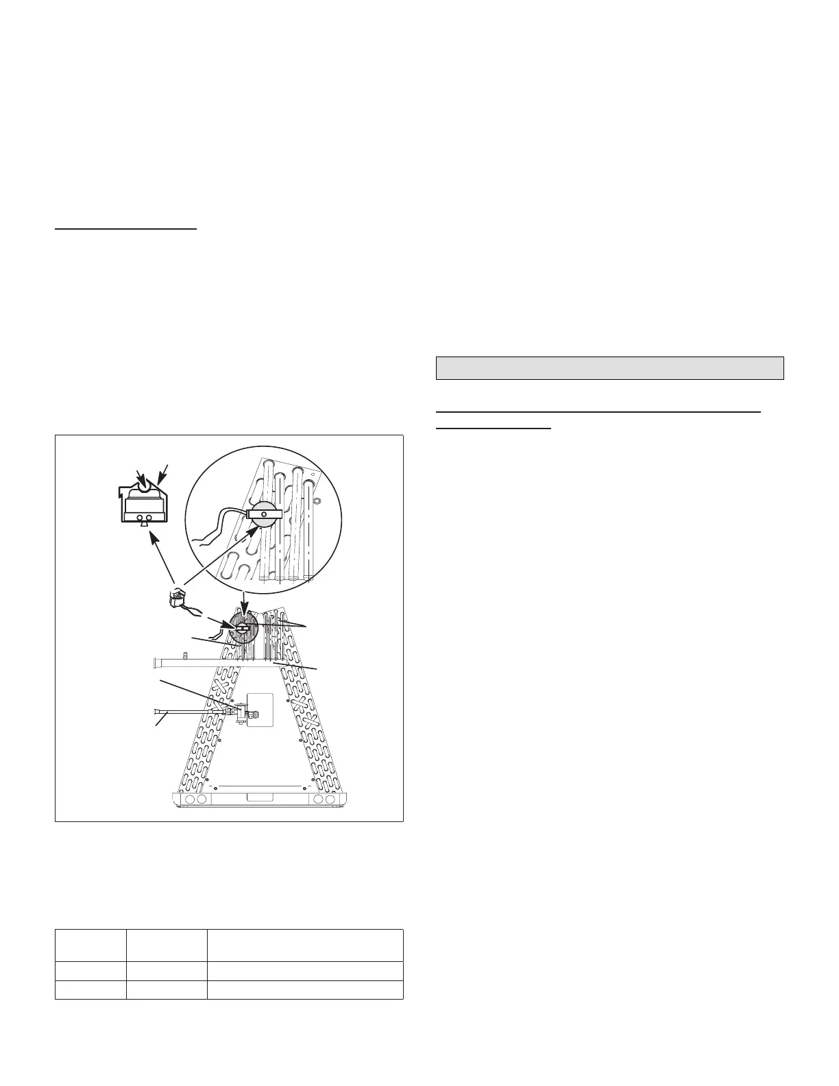
CLIP
COPPER
LINE
EXPANSION
VALVE
FREEZESTAT
SUCTION
MANIFOLD
LIQUID LINE
LAST HAIRPINS
COPPER LINES
Figure 6. Typical Freezestat Installation - Indoor
Coil
The table below lists available freezestats for use with the
damper control module.
Table 4. Available Freezestats
Catalog
Number
Piping Size Description
93G35 ⅜” Opens at 29°F, and closes at 58°F
50A93 ⅝” Opens at 36°F, and closes at 58°F
Suggested Freezestat Installation Method
The following is the recommended method for installation
of the freezestat for connection to the damper control
module.
1. A freezestat, sized per “Table 4. Available Freezestats”
and ordered separately, can be installed. Install the
freezestat on one of the copper lines between the
last hairpins and the suction manifold (see “Figure 6.
Typical Freezestat Installation - Indoor Coil”) of the
indoor coil.
2. The freezestat senses the line temperature and cycles
the compressor off when the line temperature fails
below its setpoint. The freezestat will open and close
as listed in “Table 4. Available Freezestats”
3. Connect freezestat wires to the freezestat terminals
on the damper control module after removing the
factory installed bridge (see “Figure 7. Damper Control
Jumpers and Connections” on page 7).
Setup and Conguration
Damper Control Module Jumper Settings, LEDs
and Connections
Use the following procedure to install the damper control
module. For information concerning connections see
“Table 5. Damper Control Connections, Insertion Bridge
and Jumpers” on page 6.
1. Remove the module cover.
2. Install the damper control module near the indoor unit
using provided fasteners.
NOTE: DO NOT install damper control module assembly
to indoor unit or equipment that could induce
vibration to the module. Install assembly on at
surface away from indoor unit to minimize vibration.
Securing assembly to a wall stud is desirable.
NOTE: By relocating the jumper to system terminals you
can shift the VA load from the damper transformer
to the system transformer if needed.
3. Use the default jumper setting for using an external
24VAC transformer (DMPR XFMR). Connect the
external 24VAC transformer wires to terminals DMPR
XFMR R and C (see “Figure 7. Damper Control
Jumpers and Connections” on page 7).
4. Verify that the ZONE ID jumper is set to Zone 1-4 only.
NOTE: In-zone thermostats control zones 2, 3 and 4.
The Lennox communicating series thermostat will
always control zone 1.
5. Connect wiring from the Lennox communicating
indoor unit to damper control module RSBus terminals
marked INDOOR, R, I+, I - and C (see “Figure 7.
Damper Control Jumpers and Connections” on page
7).
6. Connect in-zone thermostats from zones 2, 3 and
4 as needed to terminals PWR, D+, D- and C (see
“Figure 7. Damper Control Jumpers and Connections”
on page 7).
 Loading...


