7
Table 6. LEDs
LED Indicator
Label/Name
Color Description
DMPR1, 2, 3, 4
Damper position LED. Illuminated when damper is power closed. LED will remain ON as as long as the damper is
power-closed.
CNTRL Red Illuminated when system zoning is OFF.
STATUS Green
This green LED should blink at 1Hz, 50% duty cycle as a ”heartbeat” indicating that the device is
operat ing normally.
During device soft disable state, this LED will blink 3 seconds ON and 1 second OFF. See “Table 6.
LEDs” on page 7 for further details.
RSBUS COMM Green
RSBus activity. Active communications with external device (Lennox communicating external
device).
IN-ZONE THERMOSTAT
COMM
Green Active communication with in-zone thermostats.
PS Red Illuminate when pressure switch is open (high pressure detected).
DAMPER CONTROL
MODULE (DCM)
Ci-i+R
INDOOR
DMPR
XFMR
SYS
XFMR
SENSE 24VAC
FREEZESTAT
SENSE 24VAC
G
R C
DMPR XFMR
SENSE 24VAC
PRESSURE SW
C SENSE
DATS
D+
PWR
D-
C
ZONE 5
D+
PWR
D-
C
ZONE 2/6
D+
PWR
D-
C
ZONE 3/7
D+
PWR
D-
C
ZONE 4/8
1 – 4
5 - 8
NC
NO
DCOM
NC
NO
DCOM
NC
NO
DCOM
NC
NO
DCOM
1/5 DAMPER 2/6 DAMPER 3/7 DAMPER 4/8 DAMPER
Lennox Communicating
Thermostat
Ci-i+R
Ci-i+R
In-zone
Thermostat
C
D-
D+
PWR
SYS
XFMR
DMPR
XFMR
(DEFAULT)
or
External 24VAC
Damper Transformer
RC
JUMPER MUST BE SET
TO 1 -4. THE SETTING
FOR 5-8 IS FOR FUTURE
USE.
NC
NO
C
DAMPER
RSBUS COMM LED
(GREEN)
STATUS LED
(GREEN)
PS LED (RED)
CNTRL LED (RED)
(ZONING OFF)
DMPR1 LED (RED)
DMPR2 LED (RED)
DMPR3 LED (RED)
DMPR4 LED (RED)
3
3 AMP FUSE
IN-ZONE THERMOSTAT
COMM LED (GREEN)
NOTE 1:
FREEZESTAT TERMINAL
WILL HAVE FACTORY
INSTALLED INSERTION
BRIDGE.
DO NOT REMOVE UNLESS
CONNECTING A
FREEZESTAT (93G35 OR
50A93) TO THIS TERMINAL.
FACTORY INSTALLED
INSERTION BRIDGE
(SEE NOTE 1)
FACTORY
DEFAULT
1 – 4
5 - 8
Discharge Air
Temperature
Sensor (88K38)
Pressure Switch
(27W13) Required for
Heat Pump System)
On heat pump systems
do not use jumper to
bypass pressure
switch.
NOTE: When using iHarmony with a non-communicating outdoor unit, the following links on the indoor
Lennox control need to be configured as follows:
1. Cut the R-O or W915 link when the outdoor unit is a heat pump.
2. Cut Y1 to Y2 or W951 when independent high and low stages are required for 2-stage outdoor cooling
unit.
3. DO NOT cut R to DS or W914 when using iHarmony control.
NOTE: Interlock switch alarm 370 is activated when cutting W914 link on a two-stage communicating Lennox IFC.
NOT USED
Lennox Communicating
Indoor Unit
Lennox Communicating Air Handler:
Y1-Y2 2-stage Compr
R-O Heat Pump
R-DS Dehum or Harmony
Lennox Communicating Furnace:
W915 2 Stage Compr
W951 Heat Pump
W914 Dehum or Hormony
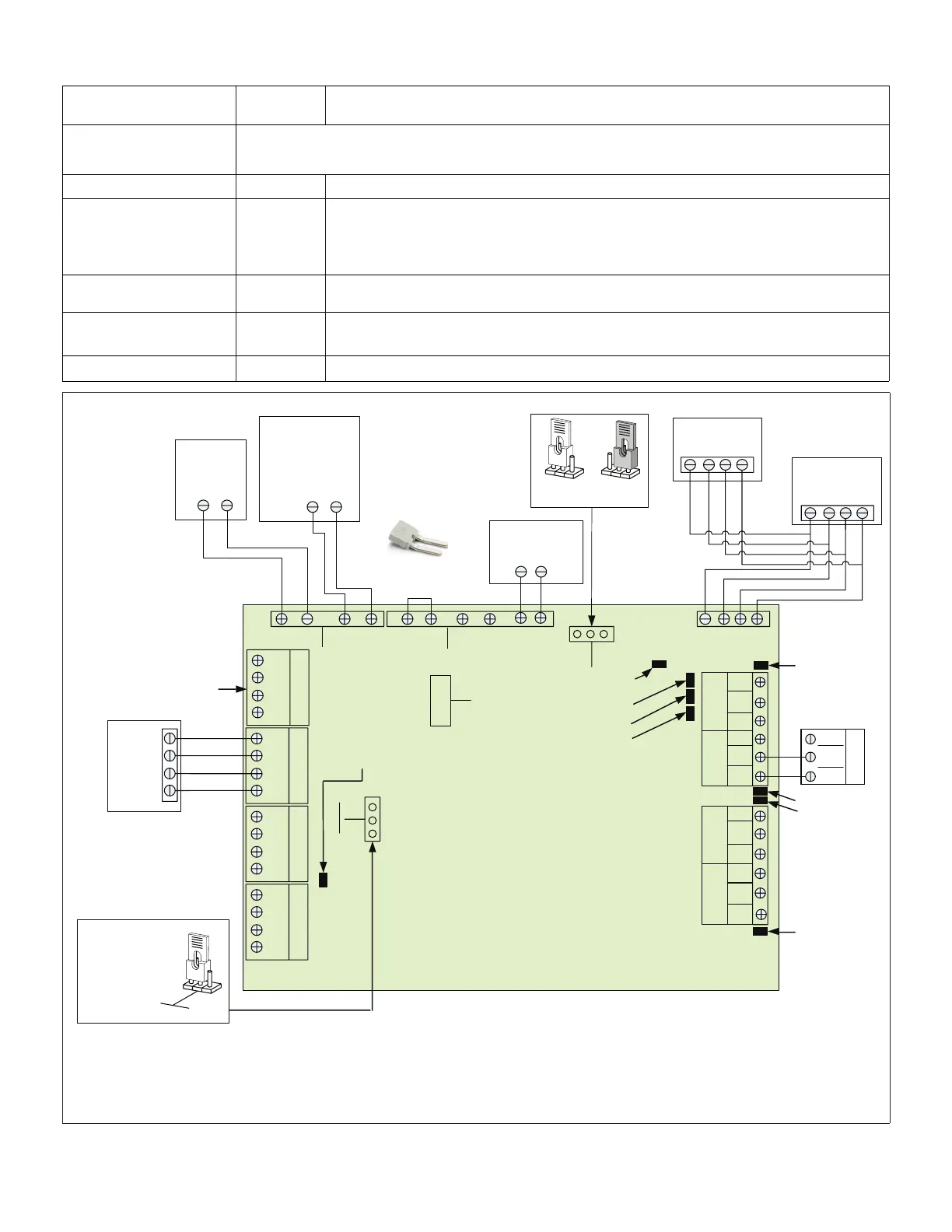
Figure 7. Damper Control Jumpers and Connections
 Loading...


