7
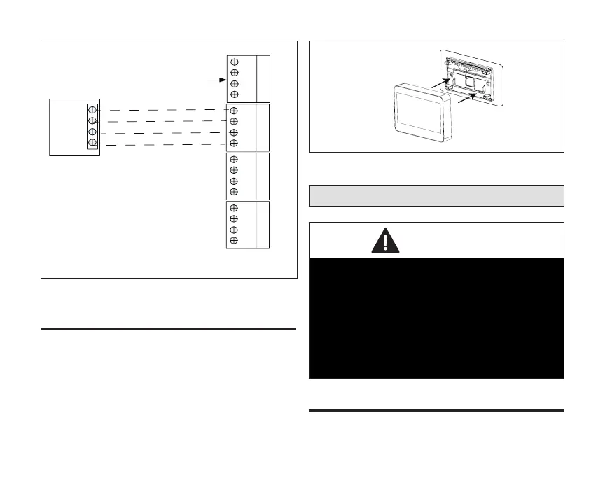
DAMPER CONTROL
MODULE (DCM)
D+
PWR
D-
C
ZONE 5
D+
PWR
D-
C
ZONE 2/6
D+
PWR
D-
C
ZONE 3/7
D+
PWR
D-
C
ZONE 4/8
Zone
Sensor
C
D-
D+
PWR
NOT USED
18AWG Unshielded Thermostat Wire
18AWG Unshielded Thermostat Wire
22AWG Shielded Thermostat Wire
22AWG Shielded Thermostat Wire
Figure 2. Connecting Zone Sensor to Damper
Control Module
The zone sensor assembly simply snaps onto the
back plate. Once secure to the back plate apply
power to the system. The zone sensor should boot
up and go into the commissioning process.
If power is applied and the zone sensor screen
remains o, inspect and verify all wire connections.
Figure 3. Installing Zone Sensor
Setup Guide
CAUTION
When replacing a failed zone sensor, remember to
set the new zone sensor to the same address as
the one being replaced. Also, If an existing zone
sensor has failed and being replaced by a zone
sensor relocated from another zone in the home,
remember to set relocated zone sensor’s address
to match the one that has failed. Not doing so
could contribute to incorrect zone operations and
possible equipment damage.
After power is applied to the zone sensor for the
rst time it will display the Lennox
®
“splash screen”
and then the zone number selection screen. Set the

 Loading...