Page 16
SIEMENS OVERLOAD RELAY
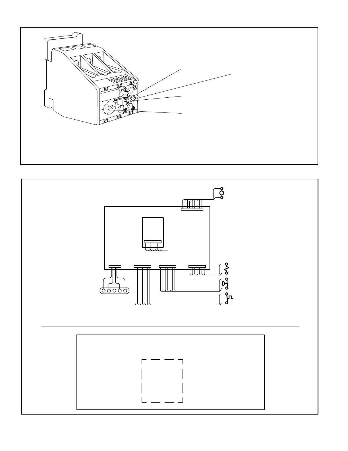
Adjust relay amp setting according to value given on the blower motor nameplate. Proper
relay amp setting equals motor nameplate FLA X service factor of 1.15 X .95.
Use small slotted screwdriver to adjust control mode from automatic reset (A) to manual
reset (H).
Control must be in the manual reset mode (H) to perform a test. Press the red test button.
Green trip indicator should pop out. Press the blue reset screw to reset the relay.
BLUE RESET BUTTON IN
FACTORY-SET AUTO MODE
(Turn clockwise to H for
manual reset)
GREEN TRIP INDICATOR
(Flush with surface -- not tripped;
Above surface -- tripped)
AMP ADJUSTMENT DIAL
RED TEST BUTTON
FIGURE 5
P110 P111 P112 P113
P115
SENSORS
INPUTS
OUTPUTS
COMPRESSOR
SAFETY INPUTS
BURNER
INPUTS
ROOM
THERMOSTAT (A2)
A55
A56
TB1 connects to P110. Room thermostat connects to TB1.
P114
IMC BOARD INPUTS AND OUTPUTS
A55:
A56:
Optional
Economizer
and/or Power
Exhaust Fan
1 Blower
1 Compressor
1 Outdoor fan
1 Gas valve
1 Electric heat section
IMC AND ADD-ON BOARD LOCATION AND OPERATION
FIGURE 6
TB1
 Loading...


