Page 23
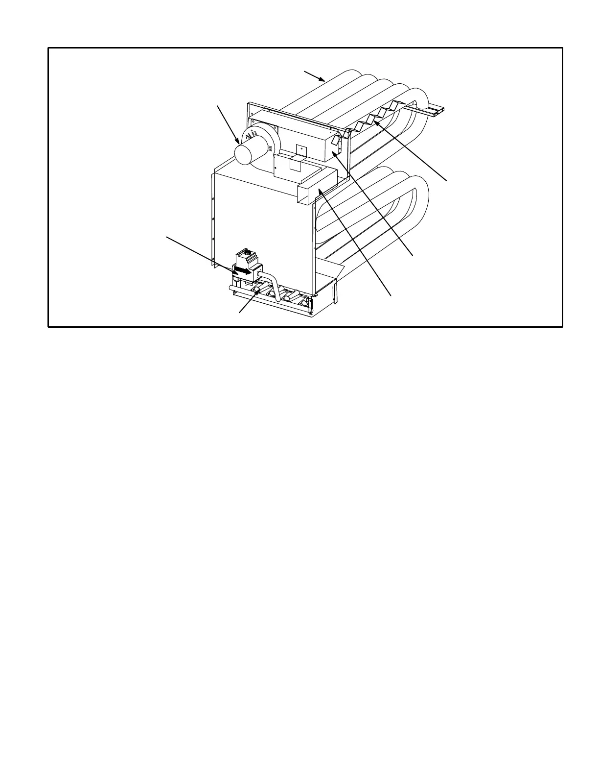
FIGURE 13
FLUE BOX
VENT CONNECTOR
BAFFLE
HEAT EXCHANGER TUBE
COMBUSTION AIR BLOWER
GAS
VALVE
BURNERS
LGA HEAT EXCHANGER
E-GAS HEAT COMPONENTS (LGA units)
LGA036 units are available in 78,000 Btuh (22.9 kW)
(standard gas heat only). LGA042/048/060/072 units
are available in 78,000 Btuh (22.9 kW) (standard gas
heat); 125,000 Btuh (36.6 kW) (high gas heat) or92,000
Btuh / 125,000 Btuh (27 / 36.6 kW) (two-stage gas heat)
sizes.
1-Burner Ignition Control A3
The ignition control is located below the control box. Three dif-
ferent manufacturers’ (Fenwal, Johnson Controls, and RAM)
controls are used in the LGA units. All three ignition controls
operate the same.
The ignition control provides three main functions: gas
valve control, ignition, and flame sensing. The unit will
usually ignite on the first attempt; however, the ignition at-
tempt sequence provides three trials for ignition before
locking out. The lockout time for the Johnson control is 5 min-
utes. The lockout time for the Ram control and Fenwall control
is 1 hour. After lockout the ignition control automatically re-
sets and provides three more attempts at ignition. Manual
reset after lockout requires breaking and remaking power to
the ignition control. See figure 15 for a normal ignition se-
quence and figure 16 for the ignition attempt sequence
with retrials (nominal timings given for simplicity). Specific
timings for the ignition controls are shown in figure 17.
Flame rectification sensing is used on all LGA units.
Loss of flame during a heating cycle is indicated by an ab-
sence of flame signal (0 microamps). If this happens, the con-
trol will immediately restart the ignition sequence and then lock
out if ignition is not gained after the third trial. See System
Service Check section for flame current measurement.
The control shuts off gas flow immediately in the event of a
power failure. Upon restoration of gas and power, the control
will restart the ignition sequence and continue until flame is
established or system locks out.
On a heating demand, the ignition control is energized by the
main control module A55. The ignition control then allows 30
seconds for the combustion air blower to vent exhaust gases
from the burners. When the combustion air blower is purging
the exhaust gases, the combustion air prove switch is closing
proving that the combustion air blower is operating before al-
lowing the ignition control to energize. When the combustion
air prove switch is closed and the delay is over, the ignition
control activates gas valve, the spark electrode and the
flame sensing electrode. Sparking stops immediately after
flame is sensed. The combustion air blower continues tooper-
ate throughout the heating demand. If the flame fails or if the
 Loading...


