Page 24
burners do not ignite, the ignition control will attempt to ignite
theburners up totwo more times. If ignition cannot be obtained
afterthe third attempt, the control will lock out. The ignition con-
trol is not adjustable.
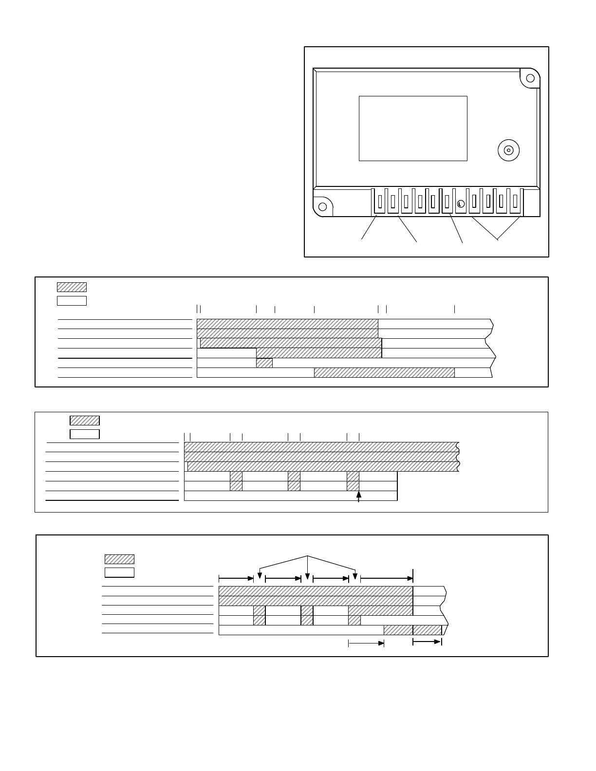
The Johnson control is illustrated in figure 14. The four
spade connections are used to connect the control to unit.
Each of the four spade terminals are identified by function.
The spark electrode wire connects to the spark-plug-type
connector on top of the control.
FIGURE 14
JOHNSON IGNITION CONTROL
LED CODES
ON” = NORMAL
OPERATION
0.5 SEC ON / 2.5 SEC OFF
= IN RETRY PERIOD
OFF” = NO POWER OR
DETECTED FAULT
GROUND
LED
POWERMAINSENSE
NORMAL IGNITION SEQUENCE
TIMINGS NOMINAL
THERMOSTAT DEMAND
COMBUSTION AIR BLOWER
GAS VALVE
IGNITION SPARK
BLOWER
IGNITION TRIAL
SECONDS 0 30 35 0 110
ON / CLOSED
OFF / OPEN
END OF
DEMAND
1
COMBUSTION AIR PROVE SWITCH
5 570
FIGURE 15
FIGURE 16
RETRIALS - IGNITION ATTEMPT SEQUENCE - TIMINGS NOMINAL
THERMOSTAT DEMAND
COMBUSTION AIR BLOWER
GAS VALVE
IGNITION SPARK
BLOWER
IGNITION TRIAL
SECONDS 0 30 35 70
ON
OFF
65 100 105
WATCHGUARD
LOCKOUT
COMBUSTION AIR PROVE SWITCH
5
FIGURE 17
THERMOSTAT DEMAND
COMBUSTION AIR BLOWER
GAS VALVE
IGNITION SPARK
BLOWER
IGNITION TRIAL
SECONDS 0 30
ON
OFF
IGNITION CONTROL TIMING
30
30
HEATING
CYCLE
6 (+3.4, -2.0) SEC.
END OF
THERMOSTAT
DEMAND
1 2 3
42 SEC. 122 SEC.
 Loading...


