Page 25
WARNING
SHOCK HAZARD. SPARK RELATED COMPONENTS
CONTAIN HIGH VOLTAGE WHICH CAN CAUSE
PERSONAL INJURY OR DEATH. DISCONNECT
POWER BEFORE SERVICING. CONTROL IS NOT
FIELD REPAIRABLE. UNSAFE OPERATION WILL
RESULT. IF THE CONTROL IS INOPERABLE, SIM-
PLY REPLACE THE ENTIRE CONTROL.
2-Heat Exchanger (Figure 13)
TheLGAunits use aluminized steel inshot burners withmatch-
ing tubular aluminized or optional stainless steel heat ex-
changers and either a one or two-stage redundant gas valve.
LGA uses one five tube/burners for high heat and one three
tube/burnersfor low heat. Each burner uses a burner venturito
mix gas and air for proper combustion. Combustion takes
place at each tube entrance. As hot combustion gases are
drawn upward through each tube by the combustion air blow-
er, exhaust gases are drawn out the top and fresh air/gas mix-
ture is drawn in at the bottom. Heat is transferred to the air
stream from all surfaces of the heat exchanger tubes. The
supply air blowers, controlled by the main control panel A55,
force air across all surfaces of the tubes to extract the heat of
combustion. The shape of the tubes ensures maximum heat
exchange.
The gas valve accomplishes staging by allowing more or less
gas to the burners as called for by heating demand.
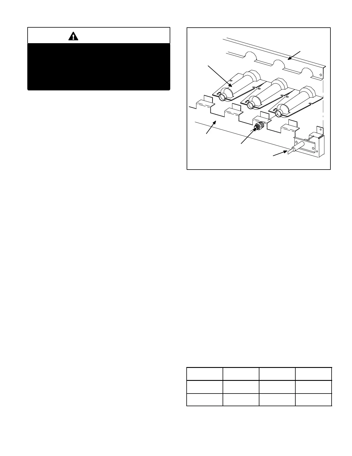
3-Burner Assembly (Figure 18)
The burners are controlled by the spark electrode, flame sens-
ing electrode, gas valve and combustion air blower. The spark
electrode, flame sensing electrode and gas valve are directly
controlled by ignition control. Ignition control and combustion
air blower is controlled by main control panel A55.
Burners
All units use inshot burners (see figure 18). Burners are
factory set and do not require adjustment. A peep hole
with cover is furnished in the heating access panel
for flame viewing. Always operate the unit with the
access panel in place. Burners canbe removed indi-
vidually for service. Burner maintenance and ser-
vice isdetailed inthe SERVICECHECKS sectionsof
this manual.
FIGURE 18
TYPICAL GAS BURNER ASSEMBLY
BURNERS
ORIFICE
SENSOR
BURNER
SUPPORT
BURNER
SUPPORT
CAP
Orifice
Each burner uses an orifice which is precisely matched to
the burner input. The orifice is threaded into the burner
manifold. The burner is supported by the orifice and will
easily slide off for service.
NOTE-Do not use thread sealing compound on the ori-
fices. Using thread sealing compound may plug the ori-
fices.
Each orifice and burner are sized specifically to the unit.
Refer to Lennox Repair Parts Listing for correct sizing in-
formation.
4-Primary High Temperature Limits
S10, S130, S131
S10(standard heat units), S130 and S131 (highheat units) are
the primary high temperature limits for gas heat. Primary lim-
its S10, S130 and S131 are wired in series to the main
control panel A55 which energizes burner control (A3). Its
N.C. contacts open to de-energize the ignition control when
excessive temperature is reached in the blower compartment.
At the same time, the N.O. contacts of primary limit close
keeping the blower relay coil K3 under the control of A55. If ei-
ther limit trips the blower will be energized. See figure 19
for limit location and table 4 for limit settings.
TABLE 4
Limit Settings
LGA Unit
Standard
Heat S10
Hi Heat
S130, S131
Hi Heat
S10
Direct Drive
210 ± 6 F
(93 ± 3.3 C)
N/A
210 ± 6 F
(93 ± 3.3 C)
Belt Drive
200 ± 6 F
(93 ± 3.3 C)
210 ± 6 F
(93 ± 3.3 C)
N/A
 Loading...


