EasyManua.ls Logo

Lennox LCA060 User Manual

Lennox LCA060
55 pages
To Next Page IconTo Next Page
To Previous Page IconTo Previous Page
Page #26 background imageLoading...
Page #26 background image
Page 26
FIGURE 19
BLOWER
OPENING
BLOWER
OPENING
S10
S131
S130
PRIMARY LIMIT LOCATION
5-Secondary High Temperature Limit S21
S21 is the secondary high temperature limit for gas
heat. The secondary limit S21 is located on the blower
transition. Secondary limit S21 is also wired to the main
control panel A55. The secondary limit functions in the
same manner as the primary limit, but is factory set to
actuate at different temperatures. The N.O. contacts of
S21 is connected to the blower relay coil K3 through
control A55. If the limit trips the burners and combustion
airblower will de-energize butthe blowerwill remain en-
ergized. All limits used are SPDT N.C. auto-reset limits.
Limit S21 in standard andhighheatunitsarefactorypre-
set to open at 175_F + 5_F (79_C + 2.8_C) on a tempera-
ture rise and automatically reset at 135_F +7_F (57_C +
3.9_C) on a temperature fall.
6-Flame Rollout Limit S47
Flame rollout limit S47 is a SPST N.C. high temperature
limit located just above the burner air intake opening in the
burner enclosure (see figure 13). S47 is wired tothe main con-
trol panel A55. When S47 sensesflame rollout (indicating
a blockage in the combustion air passages), the flame
rollout limit trips, and the ignition control immediately
closes the gas valve.
LimitS47isfactory preset to openat 200_F+ 12_F (93_C+
6.7_C) on a temperature rise. All flame rollout limits are
manual reset.
7-Combustion Air Prove Switch S18
Thecombustion air prove switch S18is aSPST N.O. pressure
switch located in the vestibule area. The switch is used to
monitor combustion air blower operation. Switch S18 is wired
to the main control panel A55. The switch actuates at 0.31ā€
W.C. negative pressure + 0.05ā€ W.C. (77Pa+ 12.4Pa) on a
pressure fall which allows power to the ignition control
(proves, by closing, that the combustion air blower is oper-
ating before allowing the ignition control to energize). The
combustion air prove switch is factory set and not adjust-
able.
8-Combustion Air Inducer B6
Combustion air inducer B6 provides fresh air to the burners
while clearing the combustion chamber of exhaust gases.
The inducer begins operating immediately upon receiving a
thermostat demand and is de-energized immediately when
thermostat demand is satisfied.
The combustion air inducer uses a 208/230V single-phase
PSC motor and a 4.72in. x 1.31in. (120mm x 33.3mm) blower
wheel. The motor operates at 3200RPM and is equipped with
auto-reset overload protection. Blowers are supplied by vari-
ous manufacturers. Ratings may vary by manufacturer. Spe-
cific blower electrical ratings can be found on the unit rating
plate.
All combustion air inducer motors are sealed and can-
not be oiled. The blower cannot be adjusted but can be
disassembled for cleaning.
9-Combustion Air Motor Capacitor C3
The combustion air blower motor in all LGA units re-
quires a run capacitor. Capacitor C3 is connected to
combustion air blower B6. All capacitors are rated at 3
MFD and 370VAC.
10-Gas Valve GV1
Gas valve GV1 is a one or two-stage redundant gas valve
used in all LGA units. Single stage units are equipped with
valves manufactured by Honeywell. Two-stage (low / high
fire) units, are equipped with valves manufactured by Honey-
well or White Rodgers. For both valves first stage (low fire) is
quick opening (on and off in less than 3 seconds). Second
stage on the White Rodgers is slow opening (on to high fire
pressure in 40 seconds and off to low fire pressure in 30 sec-
onds). Second stage on the Honeywell valve is quick opening.
On a call for first stage heat (low fire), the valve is energized by
the ignition control simultaneously with the spark electrode. On
a call for second stage heat (high fire), the second stage oper-
ator is energized directly from A55. The WhiteRodgers two
stage valve is adjustabel for high fire only. Low fire is not ad-
justable. The Honeywell two stage valve is adjustable for both
high fire and low fire. A manual shut-off knob is provided on
the valve for shut-off. Manual shut-off knob immediately
closes both stages without delay. Figures 20 and 21 show
gas valve components. Tables 5 and 6 show factory set
gas valve manifold pressures for LGA series units.
Question and Answer IconNeed help?

Do you have a question about the Lennox LCA060 and is the answer not in the manual?

Lennox LCA060 Specifications

General IconGeneral
Refrigerant TypeR-410A
Phase1
SEER16
SEER Rating16
Voltage (V)208/230

Summary

I- UNIT COMPONENTS

A-Control Box Components

Details components within the unit's control box, including switches, transformers, and relays.

B-Cooling Components

Covers compressors, capacitors, switches, and heaters related to the cooling system.

C-Blower Compartment

Explains blower types, housing access, and related components like motors and terminals.

E-GAS HEAT COMPONENTS (LGA units)

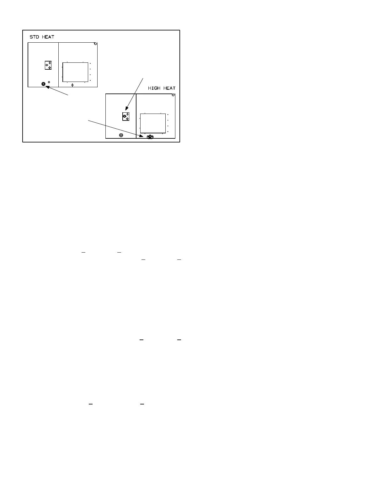
Describes gas heat components like heat exchangers, burners, ignition controls, and gas valves.

F-Optional Electric Heat Components

Details contactors, heating elements, limits, and fuse boxes for electric heat options.

II- PLACEMENT AND INSTALLATION

III- CHARGING

Charge Verification - Sub-Cooling Method

Provides a method to verify refrigerant charge using subcooling and operating pressures.

IV- STARTUP - OPERATION

A-Preliminary and Seasonal Checks

Outlines essential pre-startup checks for electrical connections, voltage, and blower belt.

B-Cooling Startup LGA/LCA

Details the procedure for initiating cooling mode, including compressor and fan operation.

C-Heating Startup LGA

Explains the process of placing the furnace in operation, including gas valve and burner procedures.

V- SYSTEMS SERVICE CHECKS

A-LGA Heating System Service Checks

Covers gas piping, testing procedures, and manifold pressure checks for proper gas heating operation.

B-Cooling System Service Checks

Details checks for refrigerant charge, subcooling, and electrical components during cooling operation.

VI- MAINTENANCE

A-Filters

Instructions for accessing, checking, and replacing air filters for optimal unit performance.

B-Lubrication

Information on lubrication requirements for unit components, noting most are pre-lubricated.

C-Supply Air Blower Wheel

Guidance on inspecting and cleaning the supply air blower wheel for accumulated dirt.

D-Evaporator Coil

Procedures for inspecting and cleaning the evaporator coil and checking the condensate system.

E-Condenser Coil

Recommendations for cleaning the condenser coil annually and inspecting it monthly.

F-Electrical

Guidance on checking all wiring connections, voltage, and amp-draw for proper electrical function.

VII- ACCESSORIES

A-LARMF03/07-14,24 Mounting Frames

Information on roof mounting frames for unit installation, ensuring stability and levelness.

B-Transitions

Details optional supply/return transitions used with roof mounting frames for unit installation.

C-Supply and Return Diffusers

Information on optional diffusers/returns for air distribution, referring to manufacturer instructions.

D-LAOADM03/07 and LAOD03/07 Outdoor Air Dampers

Describes outdoor air dampers for controlling fresh air intake and their filter maintenance.

E-LAREMD03/07 Economizer

Explains the function and modes of the optional economizer for free cooling applications.

F-LAGED03/07 and LAGEDH10/15 Gravity Exhaust Dampers

Details gravity exhaust dampers used with economizers to manage exhaust air and prevent infiltration.

G-LAPEF03/07 Power Exhaust Fan

Information on the power exhaust fan assembly used for exhaust air pressure relief.

H-Optional Cold Weather Kit

Details the optional cold weather kit for controlling gas burner compartment temperature in cold climates.

VIII- WIRING DIAGRAMS / SEQUENCE OF OPERATION

LGA/LCA036/072 P VOLTAGE

Presents the wiring diagram and sequence of operation for specific voltage configurations.

LGA/LCA036/072 Y VOLTAGE

Displays the wiring diagram and sequence of operation for Y voltage units.

LGA/LCA036/072 G, J, M, VOLTAGE

Shows the wiring diagram and sequence of operation for G, J, and M voltage units.

SEQUENCE OF OPERATION LGA/LCA036/072

Step-by-step operational sequence for cooling, heating, and economizer functions.

LGA036/072 GAS HEAT UNIT WIRING DIAGRAM

Specific wiring diagram for gas heat units, detailing component connections and safety limits.

Sequence of Operation LGA036/072 GAS HEAT

Outlines the operational sequence for gas heat, including first and second stage heating.

C2 Diagram ELECTRONIC OR ELECTROMECHANICAL THERMOSTAT

SEQUENCE OF OPERATION

Describes how the thermostat interacts with the main control module and other sensors.

ā€œLā€ SERIES ECONOMIZER

SEQUENCE OF OPERATION L" SERIES ECONOMIZER

Explains the economizer's operation sequence, controlled by the main control module and sensors.

EHA-7 / 30kW Y VOLTAGE

HEATING-ELECTRIC

Details the wiring and sequence of operation for electric heating sections.

Sequence of Operation -EHA 7 / 30kW - Y and G, J, M

Step-by-step operational sequence for electric heating elements across different stages and voltages.

SERVICE NOTES

Related product manuals