Page 6507246-02 7/2018
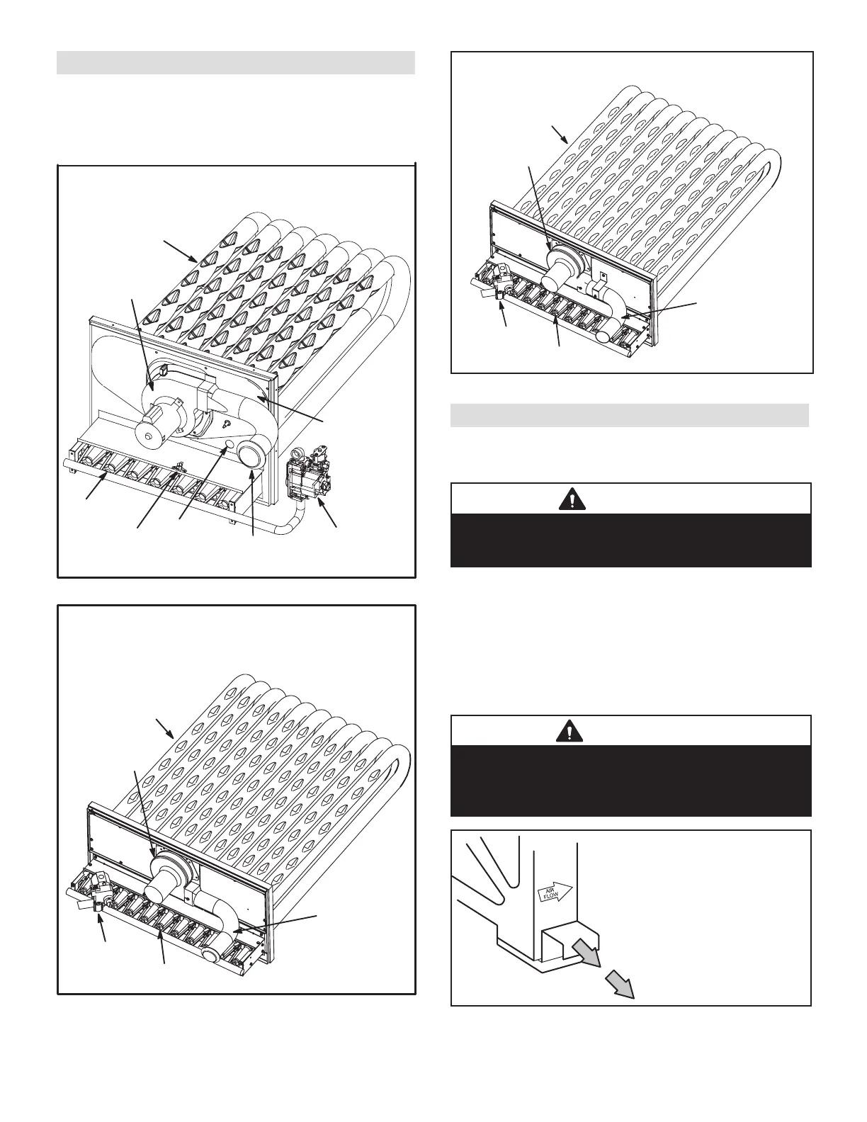
Flue Passage and Vent Inspection
Annually, before heating season, inspect the combustion
air louvers, vent cap, heat exchanger, burners and com-
bustion air inducer for corrosion, deterioration or deposits
of debris. Remove any obstructions or blockage. See Fig-
ure 5, Figure 6, or Figure 7.
HEAT EXCHANGER ASSEMBLY
036-074 UNITS - Single- and Two-Stage Shown
BURNER
COMBUSTION
AIR INDUCER
VENT
CONNECTOR
GAS VALVE
HEAT
EXCHANGER
TUBE
PRIMARY
LIMIT
ROLLOUT
SWITCH
FLUE BOX
COVER
FIGURE 5
HEAT EXCHANGER ASSEMBLY
092-152 UNITS
BURNER
COMBUSTION
AIR INDUCER
VENT
CONNECTOR
GAS VALVE
HEAT
EXCHANGER
TUBE
FIGURE 6
HEAT EXCHANGER ASSEMBLY
156-360 UNITS
BURNER
COMBUSTION
AIR INDUCER
VENT
CONNECTOR
GAS VALVE
HEAT
EXCHANGER
TUBE
FIGURE 7
Service
To maintain efciency and longevity, your equipment
must be serviced yearly by a qualied service technician.
Failure to provide proof of service can void warranty.
CAUTION
Label all wires prior to disconnection when servicing
controls. Wiring errors can cause improper and dangerous
operation. Verify proper operation after servicing.
Servicing Filter
Units are equipped with lters as shown in Table 1.
Filters should be checked monthly and replaced when
necessary. Take note of air ow direction marking on
lter frame when reinstalling lters. See Figure 8.
NOTE - Replace factory-installed lters within 30 days
of initial unit start-up. Refer to local codes or appropriate
jurisdiction for approved lters.
WARNING
Units are shipped from the factory with temporary lters.
Replace lters before building is occupied. Damage to
unit could result if lters are not replaced with approved
lters. Refer to appropriate codes.
REMOVE FILTERS
PULL TO REMOVE
FILTERS
FIGURE 8
 Loading...