Page 7
507246-02 6/2019
to the unit and use the inspection port in the access
panel to check the ame.
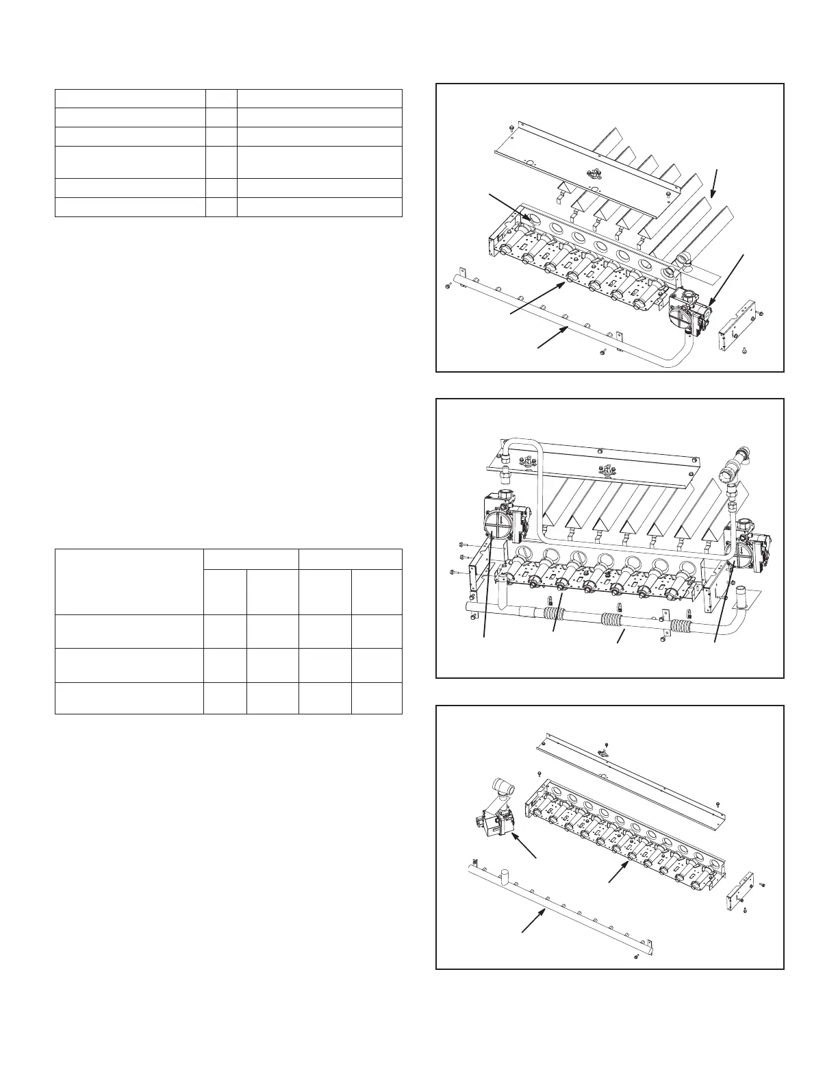
BURNER BOX ASSEMBLY
036-074 UNITS - ONE- & TWO-STAGE
GAS
VALVE
GAS
MANIFOLD
FLAME
SENSOR
BURNERS
NOX INSERT
FIGURE 9
BURNER BOX ASSEMBLY
036-074U UNITS - FOUR-STAGE
GV1
GAS VALVE
GV3
GAS VALVE
GAS
MANIFOLD
BURNERS
FIGURE 10
BURNER BOX ASSEMBLY - 092-360 UNITS
GAS
MANIFOLD
GAS
VALVE
BURNERS
FIGURE 11
TABLE 1
UNIT FILTERS
Unit Qty Filter Size - inches (mm)
036, 048 4 16 X 20 X 2 (406 X 508 X 51)
060, 072, 074 4 20 X 20 X 2 (508 X 508 X 51)
092, 094, 102, 120,
122, 150, 152
4 20 X 25 X 2 (508 X 635 X 51)
156 - 300S/U 6 24 X 24 X 2 (610 X 610 X 51)
242, 300H, 360 12 20 X 20 X 2 (508 X 508 X 51)
NOTE - Filters must be ULC approved or equivalent for use in Canada.
Lubrication
All motors are lubricated at the factory. No further
lubrication is required.
156-360 Units -
Blower shaft bearings are prelubricated. For extended
bearing life, relubricate at least once every two years
with a lithium base grease, such as Alvania 3 (Shell Oil),
Chevron BRB2 (Standard Oil) or Regal AFB2 (Texas Oil).
Use a hand grease gun for relubrication. Add only enough
grease to purge through the bearings so that a bead of
grease appears at the seal lip contacts.
Manifold Pressures
Manifold pressures are shown in table 2. Refer to Figure 1,
Figure 2, or Figure 3, or Figure 4 to locate pressure ports.
TABLE 2
MANIFOLD PRESSURES in w.g.
Unit
Natural Gas Propane (LP) Gas
1st
Stage
± 0.2
2nd
Stage
± 0.3
1st
Stage
± 0.2
2nd
Stage
± 0.3
036, 048, 060, 072,
074 Std./High Heat
NA
3.5
(0.87)
NA
10.5
(2.61)
036, 048, 060, 072,
074 Dual Heat
2.0
(0.47)
3.5
(0.87)
5.9
(1.47)
10.5
(2.61)
092-360
1.6
(0.40)
3.7
(0.92)
5.5
(1.47)
10.5
(2.61)
Burners
Clean the burners as follows:
1 - Turn off the electrical power and the gas supply to
the unit.
2 - Remove the burner compartment access panel.
3 - Remove top burner box panel. See Figure 9, Figure
10, or “Figure 10” on page 7
4 - Remove screws securing burners to burner
support and lift the entire burner assembly from the
orices. Clean as necessary. Spark gap on ignition
electrode must be properly set. Refer to the Heating
Adjustment section in the installation instructions.
5 - Replace burners and screws securing burner.
Replace the top burner box panel.
6 - Turn on the electrical power and the gas supply to
the unit. Follow the operating instructions attached
 Loading...