Page 42
LGH/LCH156, 180, 210, 240, 300S
Heating Operation and Adjustments
(Gas Units)
A-Heating Sequence of Operation
1- On a heating demand the combustion air inducer
starts immediately.
2- Combustion air pressure switch proves inducer
operation. After a 30-second pre-purge, power is
allowed to ignition control. Switch is factory set and
requires no adjustment.
3- Spark ignitor energizes and gas valve solenoid
opens.
4- Spark ignites gas, ignition sensor proves the flame
and combustion continues.
5- If flame is not detected after first ignition trial, ignition
control will repeat steps 3 and 4 two more times
before locking out the gas valve.
6- For troubleshooting purposes, an ignition attempt
after lock out may be re-established manually. Move
thermostat to “OFF” and return thermostat switch to
“HEAT” position.
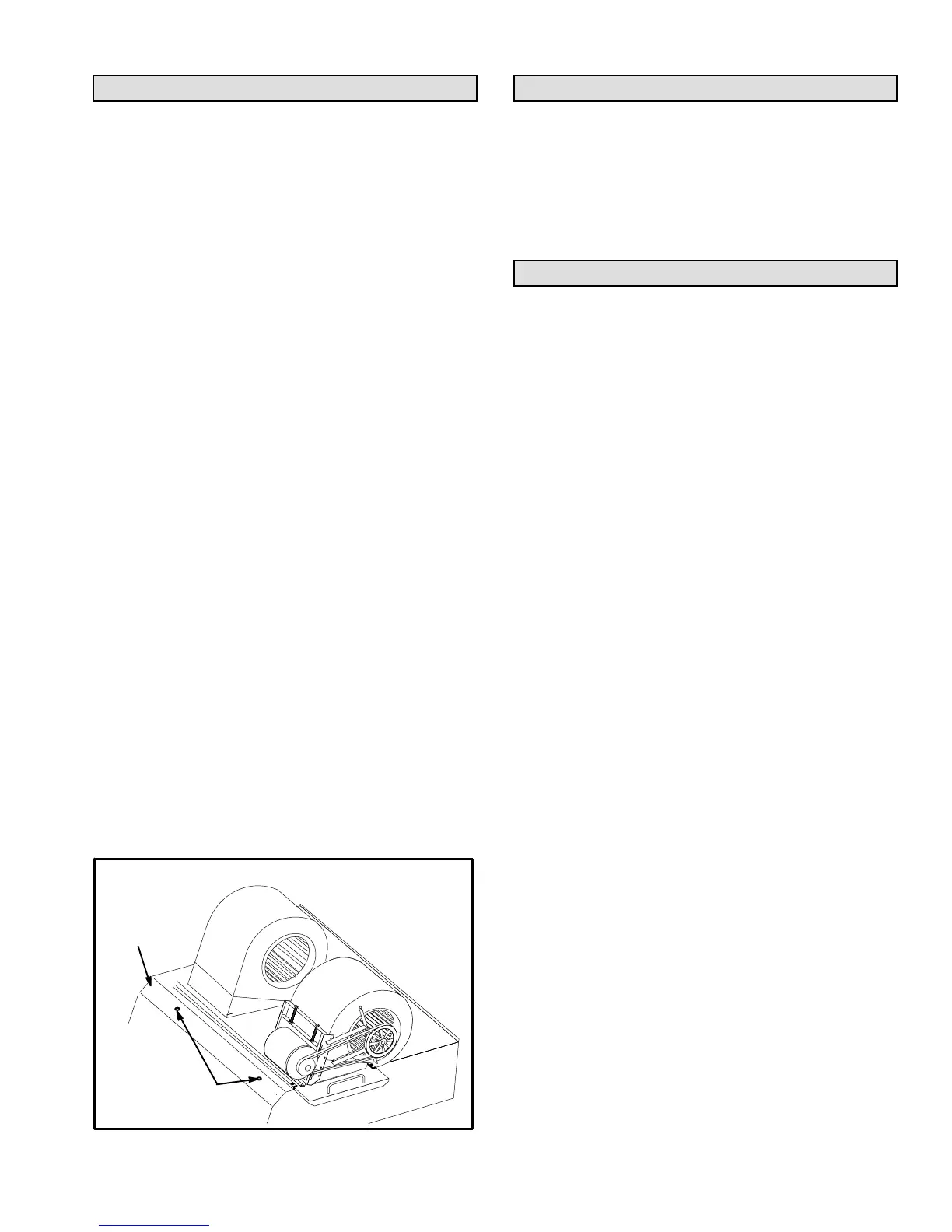
B-Limit Controls
Limit controls are factory-set and are not adjustable. Two
limits are located on the drip shield in the blower
compartment. See figure 28.
C-Heating Adjustment
Main burners are factory-set and do not require adjustment.
The following manifold pressures are listed on the gas valve.
Natural Gas Units - Low Fire - 1.6” w.c.
(not adjustable)
Natural Gas Units - High Fire - 3.7” w.c.
LP Gas Units - Low Fire - 5.5” w.c.
(not adjustable)
LP Gas Units - High Fire - 10.5” w.c.
LIMIT LOCATION
FIGURE 28
LIMITS
DRIP
SHIELD
Electric Heat Start-Up (LCH Units)
Factory- or Field-Installed Option
Electric heat will stage on and cycle with thermostat
demand. Number of stages of electric heat will vary
depending on electric heat assembly. See electric heat
wiring diagram on unit for sequence of operation.
Inverter Start-Up
A-Design Specifications
Use table 22 to fill in field-provided, design specified
blower CFM for appropriate unit.
If only high and low cooling design specifications are
provided, set the medium cooling CFM at the high or low
cooling design spec or any CFM between.
B-Set Maximum CFM
Use table 22 to determine highest blower CFM for
appropriate unit. Adjust the blower pulley to deliver that
amount of CFM with only the blower operating. See
Determining Unit CFM in the Blower Operation and
Adjustment section.
 Loading...