Page 53
507124-04 3/2016
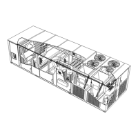
FIGURE 35
IGNITOR
SPARK GAP
SHOULD BE
1/8” (3mm)
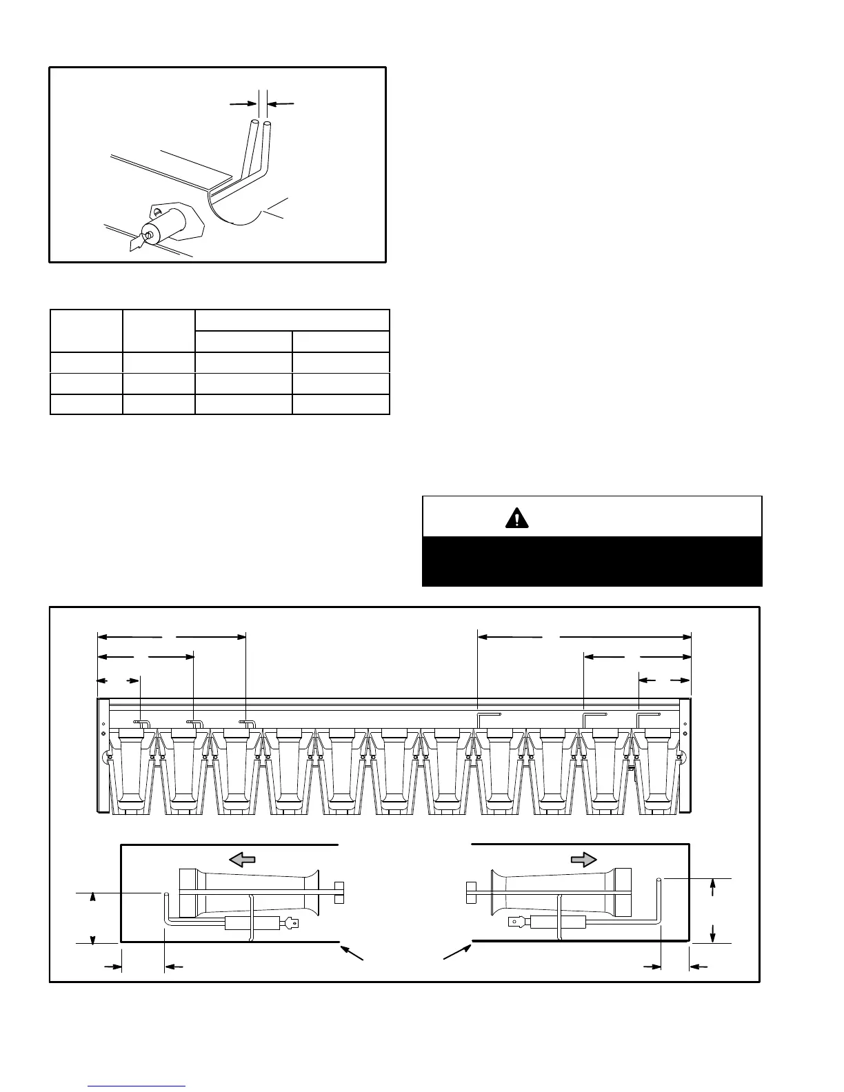
TABLE 27
Dimension
Unit
Btuh Input
Length - in. (mm)
Ignitor Sensor
A 260K 7-3/4 (197) 11 (279)
B 360K 5 (127) 5-1/2 (140)
C 480K 2-1/4 (57) 2-3/4 (70)
D-Combustion Air Inducer (Gas Units)
A combustion air proving switch checks combustion air
inducer operation before allowing power to the gas
controller. Gas controller will not operate if inducer is
obstructed.
Under normal operating conditions, the combustion air
inducer wheel should be checked and cleaned prior to the
heating season. However, it should be examined
periodically during the heating season to establish an
ideal cleaning schedule. With power supply
disconnected, the condition of the inducer wheel can be
determined by looking through the vent opening.
Clean combustion air inducer as follows:
1- Shut off power supply and gas to unit.
2- Disconnect pressure switch air tubing from
combustion air inducer port.
3- Remove and retain screws securing combustion
air inducer to flue box. Remove and retain two
screws from bracket supporting vent connector.
See figure 37.
4- Clean inducer wheel blades with a small brush and
wipe off any dust from housing. Clean accumulated
dust from front of flue box cover.
5- Return combustion air inducer motor and vent
connector to original location and secure with retained
screws. It is recommended that the combustion air
inducer gasket be replaced during reassembly.
6- Clean combustion air inlet louvers on heat access
panel using a small brush.
WARNING
This product contains a chemical known to the
State of California to cause cancer, birth defects, or
other reproductive harm.
A
B
C
FIGURE 36
IGNITOR AND SENSOR POSITION
TOP VIEW
SIDE VIEW IGNITOR SIDE VIEW SENSOR
1-3/4”
(45mm)
3/8”
(10mm)
1-3/8”
(35mm)
BURNER BOX
Gas Flow Gas Flow
13/16”
(21mm)
A
B
C
IGNITOR SENSOR
 Loading...