Page 34
F-Gravity Exhaust Dampers
and LAGEDH are used in horizontal air discharge appli-
in the return air plenum . The dampers must be used any
-
charged from the system when an economizer and/or
installation instructions for more detail.
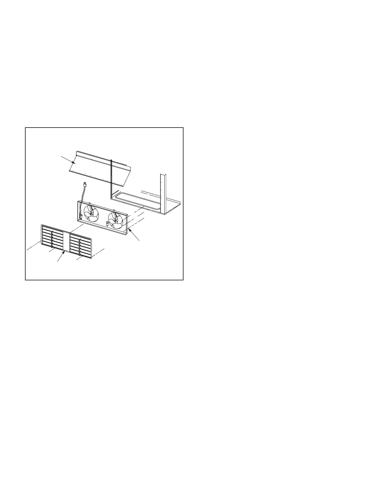
LAPEF
POWER EXHAUST
FAN ASSEMBLY
LAGED GRAVITY
EXHAUST DAMPERS
ECONOMIZER
FRESH AIR
HOOD
P18
LAGED AND LAPEF INSTALLATION
FIGURE 22
G-C1PWRE10 Power Exhaust Fans
applications only. C1PWRE10 fans require optional down-
-
relief and also run when return air dampers are closed
and supply air blowers are operating. Figure 22 shows
instructions for more detail.
H-Control Systems
The A55 Unit Controller provides all control function for
the rooftop unit. Default operation requires a standard
room thermostat or direct digital controller (DDC). The A55
can also control the unit from a zone temperature sensor.
The A55 Unit Controller is a network controller when dai-
sy-chained to the L Connection
®
Network Control System.
PC with Unit Controller PC software installed.
I-Smoke Detectors A171, A172, A173
-
stalled option. The smoke detectors can be installed in the
both the supply and return air section. Smoke detection
control module (A173) is located below the control pan-
el. Wiring for the smoke detectors are shown on the tem-
perature control section (C) wiring diagram in back of this
manual.
J-Blower Proving Switch S52
The blower proving switch monitors blower operation and
locks out the unit in case of blower failure. The switch is
N.O. and closes at .15” W.C. The switch is mounted on
the middle left corner of the blower support panel. Wiring
for the blower proving switch is shown on the temperature
control section (C) wiring diagram in back of this manual.
K-Dirty Filter Switch S27
-
at 1” W.C. The switch is mounted on the top corner of the
the temperature control section (C) wiring diagram in back
of this manual.
L-Indoor Air Quality (CO2) Sensor A63
The indoor air quality sensor monitors CO2 levels and
reports the levels to the A55 Unit Controller. The board
adjusts the economizer dampers according to the CO2
-
stat or in the return air duct. Refer to the indoor air qual-
ity sensor installation instructions for proper adjustment.
Wiring for the indoor air quality switch is shown on the
temperature control section (C) wiring diagram in back of
this manual.
M-Optional UVC Lights
The Healthy Climate germicidal light emits ultraviolet
in the air.
UVC germicidal lamps greatly reduce the growth and pro-
liferation of mold and other bio-aerosols (bacteria and vi-
ruses) on illuminated surfaces.
Germicidal lamps are NOT intended to be used for remov-
appropriately removed PRIOR to installation of the germi-
cidal lamp.
Refer closely to UVC light installation instruction warnings
when servicing units.
 Loading...


