Page 35
-
and restart the unit (if the switch has closed). The Unit
Controller has a three-strike counter before the unit locks
switch to open three times per thermostat demand. If the
-
ter the switch has closed to restore unit operation.
O-Indoor Air Quality Sensor
remove the failed sensor from the unit. All units will have
are secured to the tray by two screws. The power cable
assembly will need to be detached from the connector lo-
cated on the bottom of the sensor as well.
Removing the Sensor
1 - Go to Menu > Network Integrations > Wireless
Sensor Network Setup > Wireless Sensor Network.
2 -
that is being replaced.
3 -
Remove Sensor option at the bottom of the screen.
4 - Type in the sensor name that is to be removed and
select Proceed.
Replacing the Sensor
1 - Open the CORE Service App and navigate to Menu
> (Setup) Network Integration > Wireless Sensor
Network Setup > Wireless Sensor Network.
2 - Click Add node on the Network Nodes screen. This
triggers the CORE Service App to scan for both the
WIAQ Return Sensor and WIAQ Discharge Sensor.
3 -
adding process.
4 - Verify that the CORE Service App displays the “Node
Provisioned” on the Provision Sensor Network.
5 - Verify if CORE Service app is showing PM2.5
counts for both return and supply mounted sensors
and TVOC counts from return mounted sensor.
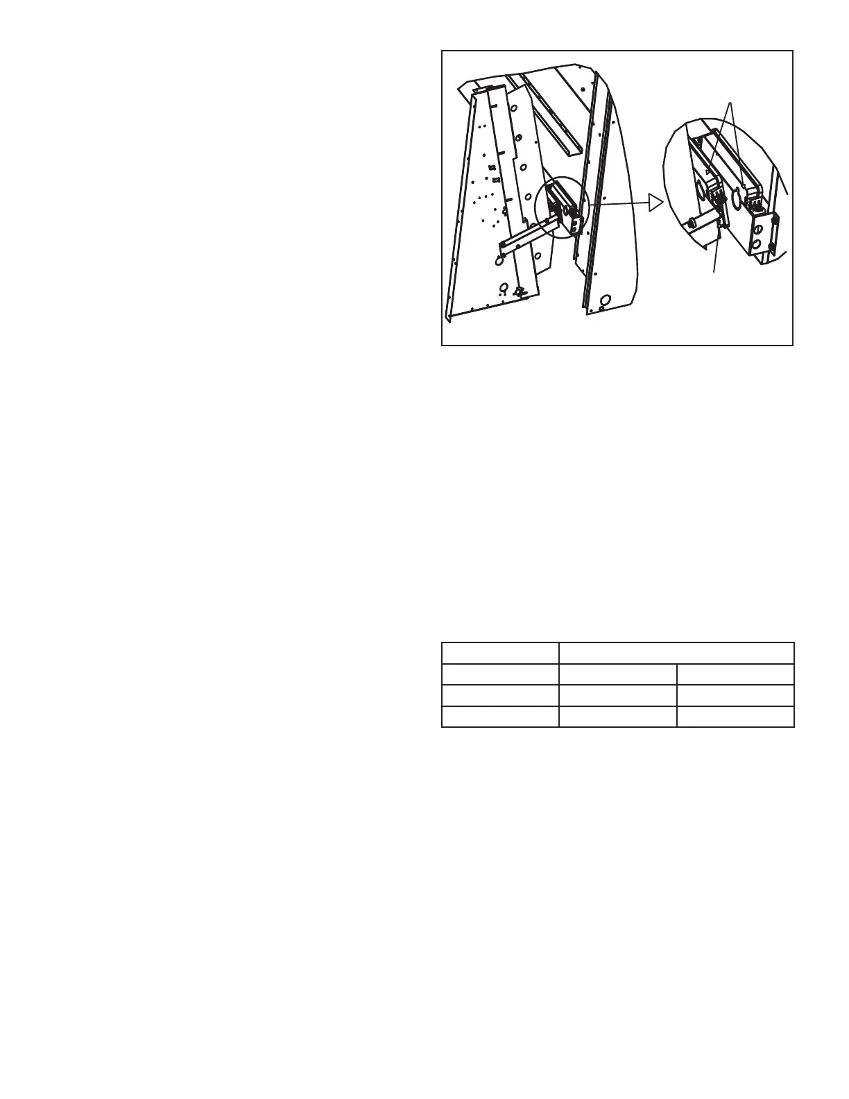
Location of both
the Supply and Return
IAQ Sensors
Always install IAQ
Sensor so Status Indicator
is viewable.
FIGURE 23
P-Bipolar Ionizer
designed for LG/LC/LH/LD/KG/KC/KH 024-300 units. The
ionizer is equipped with dry contacts which allow a Build-
ing Automation System (BAS) to interface and indicate
ionizer functionality.
Note - The BAS will be able to monitor units equipped with
M4 Unit Controllers only. Units with an M3 Unit Controller
or no controller need to be connected to a separate mon-
itoring system.
The Ionizers are also equipped with a green LED which
power is delivered to the Ionizers and ions are generated.
See table 10 for unit application.
TABLE 10
LHT Unit Part No.
21U37
240
300 21U39
 Loading...


