Home
Lennox
Air Conditioner
M33C024S4
Lennox M33C024S4 User Manual
4
of 1
of 1 rating
104 pages
Give review
Manual
Specs
To Next Page
To Next Page
To Previous Page
To Previous Page
Loading...
67
1
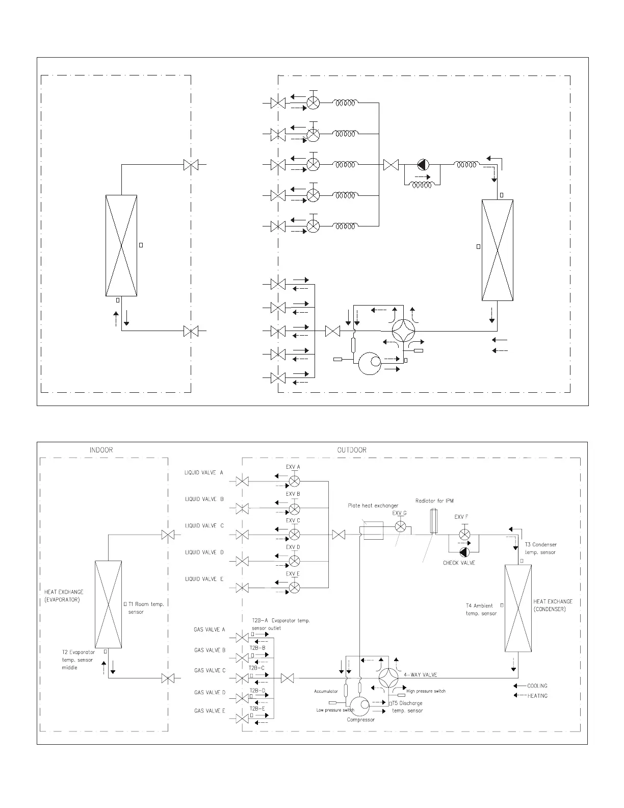
1.5.
MPC Five-Zone Refrigerant Cycle Diagram
L
IQ
UID
VA
L
VE
A
GAS VALVE A
Indoor Coil
Outdoor Coil
COOLING
HE
AT
IN
G
T2 Evaporator
temp
.
s
en
sor
T1 R
oo
m
temp
.
s
en
sor
T3
Condenser
temp
.
s
en
sor
T4 Ambi
en
t
temp
.
s
en
sor
INDOOR
OUTDOOR
EXV A
CA
PILIARY A
CHEC
K VALVE
CA
PILIA
RY
TUBE
EXV B
CA
PILIARY B
L
IQ
UID
VA
L
VE
B
GAS VALVE B
EXV C
C
AP
ILI
ARY
C
L
IQ
UID
VA
L
VE
C
GAS VALVE C
EXV D
C
AP
ILI
ARY
D
L
IQ
UID
VA
L
VE
D
GAS VALVE D
EXV E
CA
PILIARY E
L
IQ
UID
VA
L
VE
E
GAS VALVE E
Compressor
4-WAY VALVE
T5
Di
sc
harge
temp
.
s
en
sor
Accumulator
Hi
gh pr
essu
re
switch
Lo
w
pr
essu
re
switch
1
1.6.
MLB Six-Zone Refrigerant Cycle Diagram
This plate heat exchanger is to
cool the gas for compressor
during heating mode.
This EXV G, only open during the heating
mode and at low ambient temperature.
The Radiator is to cool the PCB at heating and cooling mode
Radiator is to cool the PCB at heating and cooling mode
The Radiator is to cool the PCB at heating and cooling mode
66
68
Table of Contents
Table of Contents
1
Indoor Unit Information
3
M22A and M33C Cassette Non-Ducted Indoor Units
3
Model Number Identification
3
M22A Indoor Unit Specifications
3
M33C Indoor Unit Specifications
4
M22A Indoor Unit Dimensions
5
M33C Indoor Unit Dimensions
6
M22A and M33C Indoor Unit Clearances
7
M22A and M33C Indoor Unit Control Board Switches Location
8
M22A and M33C Condensate Drain Test Procedure
9
MMDB Ducted Indoor Units
10
MMDB Model Number Identification
10
MMDB Indoor Unit Specifications
11
Indoor Unit Blower Data
12
MMDB Indoor Unit Dimensions
18
MMDB Indoor Unit Clearances
19
Condensate Pump Lift - MMDB and M22A/M33C
20
MMDB Condensate Drain Test Procedure
20
MMDB Indoor Unit Gravity Drain
21
MWMC and 3WMC-036 Wall Mounted Indoor Units
22
Model Number Identification
22
Indoor Unit Specifications (009 - 012 Ton) Units
23
Indoor Unit Specifications (018 - 030 Ton) Units
23
Indoor Unit Specifications (3Wmc)
23
Indoor Unit Dimensions (Mwmc And 3Wmc)
24
Indoor Unit Clearances (All Models And Sizes)
25
MWMC and 3WMC036S4 Unit Control Board Switches Location
25
Dry Mode Operation - Mwmc And 3Wmc
26
Test Run - Mwmc And 3Wmc
26
Double-Check Pipe Connections
26
Ambient Temperature Is Below 63°F (17°C)
27
MCFA and MCFB Ceiling / Floor Indoor Units
28
Model Number Identification
28
Indoor Unit Specifications (018 - 048 Ton) Units
28
Indoor Unit Dimensions
29
Indoor Unit Clearances
30
MCFA and MCFB Indoor Unit Control Board Switches Location
31
MFMA Floor Indoor Unit
32
Model Number Identification
32
Indoor Unit Specifications (012 Ton) Unit
32
Indoor Unit Dimensions
33
Indoor Unit Clearances
33
Indoor and Outdoor Power and Communication Wiring Requirements
34
Overview
34
Wiring Guide
35
Terminal Connections
37
Wired and Wireless Remotes
39
22U49 Wireless Remote
39
22U50 Wireless Remote
39
22U52 Wireless Remote
39
M0STAT61Q-1 and M0STAT61Q-2 Wired Remotes
39
Connection to Centralized Controller, ON/OFF and Alarm Devices
40
Set Indoor Unit Address for Centralized Control (Used with VRF Only)
40
Centralized Controller
41
ON/OFF Devices
41
Alarm Devices
41
Connecting Cables
41
Outdoor Unit Information
42
Single and Multiple Zone Outdoor Units
42
Model Number Identification
42
MPC Single-Zone Specifications (0.75 - 1.5 Ton)
43
MPC Single-Zone Specifications (2 - 4 Ton)
44
3PC Single-Zone Specifications
45
MLB Single-Zone Specifications (0.75 - 2 Ton)
46
MLB Single-Zone Specifications (3 - 4 Ton)
47
MPC Multi-Zone Specifications (1.5 - 2.5 Ton)
48
MPC Multi-Zone Specifications (3 - 4 Ton)
49
MLB Multi-Zone Specifications (1.5 - 3 Ton)
50
Mlb Multi-Zone Specifications (4 Ton)
51
Single-Zone Outdoor Unit Dimensions
52
Multi-Zone Outdoor Unit Dimensions
53
Outdoor Unit Clearances
54
Indoor / Outdoor Unit Combinations
56
Mpc Multi-Zone System Combinations
56
Mlb Multi-Zone System Combinations
62
Refrigeration Pipe Work
65
Mpc And 3Pc Single-Zone Refrigerant Cycle Diagram
65
Mpc Two-Zone Refrigerant Cycle Diagram
65
Mpc Three-Zone Refrigerant Cycle Diagram
66
Mpc Four-Zone Refrigerant Cycle Diagram
66
Mpc Five-Zone Refrigerant Cycle Diagram
67
Mlb Six-Zone Refrigerant Cycle Diagram
67
Single-Zone Piping Limitations
68
Multi-Zone Piping Limitations
68
Master Valves (3 to 5 Zone Outdoor Units)
70
MPC Multi-Zone Outdoor Unit Connections and Line Set Usage
71
MLB Multi-Zone Outdoor Unit Connections and Line Set Usage
79
Power and Communication Wiring for Systems
83
Outdoor Unit Condensate Piping
84
MPC Condensate Pump Diagrams
85
Installation Requirements
86
Torque Requirements
86
Pipe Length And Elevation
86
Electronic Function
89
Abbreviations
89
Electric Control Working Environment
89
Start-Up
89
Adding Refrigerant - Single-Zone Systems
89
Adding Refrigerant - Multi-Zone Systems
90
Single-Zone Outdoor Unit LED Locations
91
Multi-Zone Outdoor Unit Leds and SW1 Locations
92
Specifications And Operations
93
Pressure on Service Port
94
Cooling Charts
94
Heating Chart
94
Capacity Request Calculations
95
Defrost Control
98
Defrost Theory
98
Defrost Termination
98
Outdoor Fan Control
99
Four-Way Valve Control
100
Electronic Expansion Valve (Exv) Control
100
4
Based on 1 rating
Ask a question
Give review
Questions and Answers:
Need help?
Do you have a question about the Lennox M33C024S4 and is the answer not in the manual?
Ask a question
Lennox M33C024S4 Specifications
General
Brand
Lennox
Model
M33C024S4
Category
Air Conditioner
Language
English
Related product manuals
Lennox M33A036S4-1P
258 pages
Lennox M33A024S4-2P
28 pages
Lennox MS7
12 pages
Lennox MS8H
97 pages
Lennox MCFA
8 pages
Lennox MMA036S4
88 pages
Lennox MPC048S4S
104 pages
Lennox MPC030S4S
104 pages
Lennox MLA036S4M
168 pages
Lennox MPB048S4M
168 pages
Lennox MPB036S4M
168 pages
Lennox MPB012S4S
168 pages
 Loading...