Page 14
505366M 01/08
In Canada, wiring must conform with current local codes
and the current Canadian Electrical Code (CEC).
WIRE TIES
HIGH VOLTAGE
FIELD WIRING
LOW VOLTAGE
FIELD WIRING
FACTORY
WIRING
GROMMET
Figure 25. Separating High/Low Voltage Field Wiring
(Typical Field Wiring)
WIRING CONNECTIONS
1. Install line voltage power supply to unit from a properly
sized disconnect switch. Any excess high voltage field
wiring should be trimmed or secured away from the
low voltage field wiring.
2. Ground unit at unit disconnect switch or to an earth
ground.
3. Connect conduit to the unit using provided conduit
bushing.
4. Install room thermostat (ordered separately) on an
inside wall approximately in the center of the
conditioned area and five feet (1.5 m) from the floor.
It should not be installed on an outside wall or where
it can be affected by sunlight, drafts or vibrations.
NOTE − For proper voltages, select thermostat wire gauge
per the following table:
Table 5. Wire Run Lengths
Wire run length AWG # Insulation type
Less than 100 feet (30 m) 18
Color−coded with a minimum
temperature rating of 35
º
C.
More than 100 feet (30 m) 16
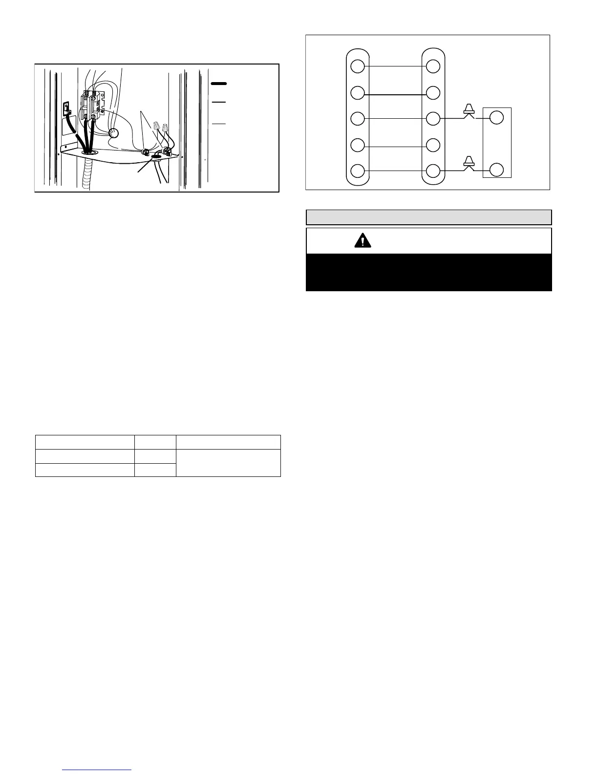
5. Install low voltage wiring from outdoor to indoor unit
and from thermostat to indoor unit as illustrated in
figures 26 and 24.
6. Do not bundle any excess 24VAC control wire inside
control box. Run control wire through installed wire tie
and tighten wire tie to provided low voltage strain relief
and to maintain separation of field installed low and
high voltage circuits.
NOTE − 24VAC, Class II circuit connections are made in
the low voltage junction box
NOTE − Units are approved for use only with copper
conductors.
NOTE − To facilitate conduit, a hole is in the bottom of the
control box. Connect conduit to the control box using a
proper conduit fitting.
NOTE − See unit wiring diagram for power supply
connections. If indoor unit is not equipped with blower
relay. It must be field−provided and installed (P−8−3251 or
equivalent)
W1
Y
G
C
R
Y
G
C
THERMOSTAT INDOOR UNIT
POWER
HEAT
COOLING
INDOOR
BLOWER
COMMON
OUTDOOR
UNIT
Y1
C
W
R
Figure 26. Typical Field Low Voltage Wiring
Start−Up and Charging Procedures
IMPORTANT
If unit is equipped with a crankcase heater, it should
be energized 24 hours before unit start−up to
prevent compressor damage as a result of slugging.
1. Rotate fan to check for binding.
2. Inspect all factory− and field−installed wiring for loose
connections.
3. After evacuation is complete, open the liquid line and
suction line service valves to release the refrigerant
charge (contained in outdoor unit) into the system.
4. Replace the stem caps and tighten as specified in
Operating Service Valves on page 2.
5. Check voltage supply at the disconnect switch. The
voltage must be within the range listed on the unit’s
nameplate. If not, do not start the equipment until you
have consulted with the power company and the
voltage condition has been corrected.
6. Set the thermostat for a cooling demand. Turn on
power to the indoor indoor unit and close the outdoor
unit disconnect switch to start the unit.
7. Recheck voltage while the unit is running. Power must
be within range shown on the nameplate.
8. Check system for sufficient refrigerate by using the
procedures listed under Testing and Charging
System.
SETTING UP TO CHECK CHARGE
1. Close manifold gauge set valves. Connect the center
manifold hose to an upright cylinder of HCFC−22.
2. Connect the manifold gauge set to the unit’s service
ports as illustrated in figure 1.
low pressure gauge to suction service port
high pressure gauge to liquid service port
INDOOR AIRFLOW CHECK
Check airflow using the Delta−T (DT) process using the
illustration in figure 27.
DETERMINING CHARGE METHOD
Use the illustration in figure 28 to determine the correct
charging method.
 Loading...