Page 4
505366M 01/08
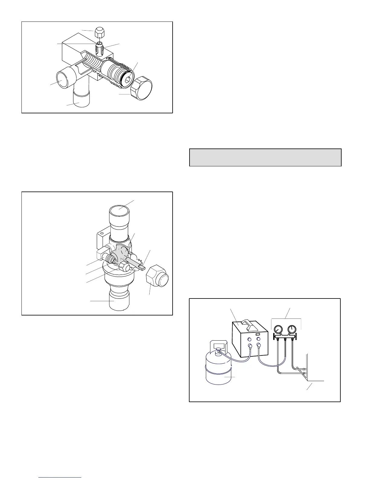
SERVICE PORT
SERVICE PORT
CORE
TO OUTDOOR UNIT
STEM CAP
(VALVE STEM SHOWN OPEN)
INSERT HEX WRENCH HERE
SERVICE PORT CAP
TO INDOOR
UNIT
OPEN TO BOTH
INDOOR AND
OUTDOOR UNITS
Figure 4. Angle−Type Service Valve
(Back−Seated Opened)
Operating Ball−Type Service Valve
To Access Ball−Type Service Port:
A service port cap protects the service port core from
contamination and serves as the primary leak seal.
BALL (SHOWN
CLOSED)
SERVICE PORT
CORE
TO INDOOR UNIT
TO OUTDOOR UNIT
TO OPEN ROTATE STEM
COUNTERCLOCKWISE 90°.
SERVICE PORT
SERVICE PORT CAP
STEM CAP
VALVE
STEM
OPEN TO LINE SET WHEN VALVE IS CLOSED,
TO BOTH LINE SET AND UNIT WHEN VALVE IS
OPEN.
TO CLOSE ROTATE STEM
CLOCKWISE 90°.
Figure 5. Ball−Type Service Valve
1. Remove service port cap with an appropriately sized
wrench.
2. Connect gauge to the service port.
3. When testing is completed, replace service port cap and
tighten as follows:
With Torque Wrench: Finger tighten and then
tighten per table table 1.
Without Torque Wrench: Finger tighten and use an
appropriately sized wrench to turn an additional
1/6 turn clockwise as illustrated in figure 2.
To Open and Close Ball−Type Service Valve:
A valve stem cap protects the valve stem from
contamination and assures a leak−free seal.
1. Remove stem cap with a wrench.
2. Use an appropriately sized wrench to open. To open
valve, rotate stem counterclockwise 90°. To close
rotate stem clockwise 90°.
3. Replace the stem cap and tighten as follows:
With Torque Wrench: Finger tighten and then
tighten per table 1.
Without Torque Wrench: Finger tighten and use an
appropriately sized wrench to turn an additional
1/12 turn clockwise as illustrated in figure 2.
NOTE − A label with specific torque requirements may be
affixed to the stem cap. If the label is present, use the
specified torque.
Recovering Refrigerant from Existing
System
Remove existing HCFC−22 refrigerant using one of the
following methods:
METHOD 1:
Use this method if the existing outdoor unit is not equipped
with manual shut−off valves, and plan on using existing
HCFC−22 refrigerant to flush the system.
NOTE − Use recovery machine instructions for specific
setup requirements.
Perform the following task:
1. Disconnect all power to the existing outdoor unit.
2. Connect to the existing unit a gauge set, clean
recovery cylinder and a recovery machine. Use the
instructions provided with the recover machine on how
to setup the connections.
3. Remove all HCFC−22 refrigerant from the existing
system. Check gauges after shutdown to confirm that
the entire system is completely void of refrigerant.
MANIFOLD GAUGES
RECOVERY MACHINE
CLEAN RECOVERY
CYLINDER
OUTDOOR UNIT
Figure 6. Typical Refrigerant Recovery (Method 1)
 Loading...