Page 39
Integrated Control
(Automatic Hot Surface Ignition System)
BLOWER OFF DELAY
RECALL BUTTON
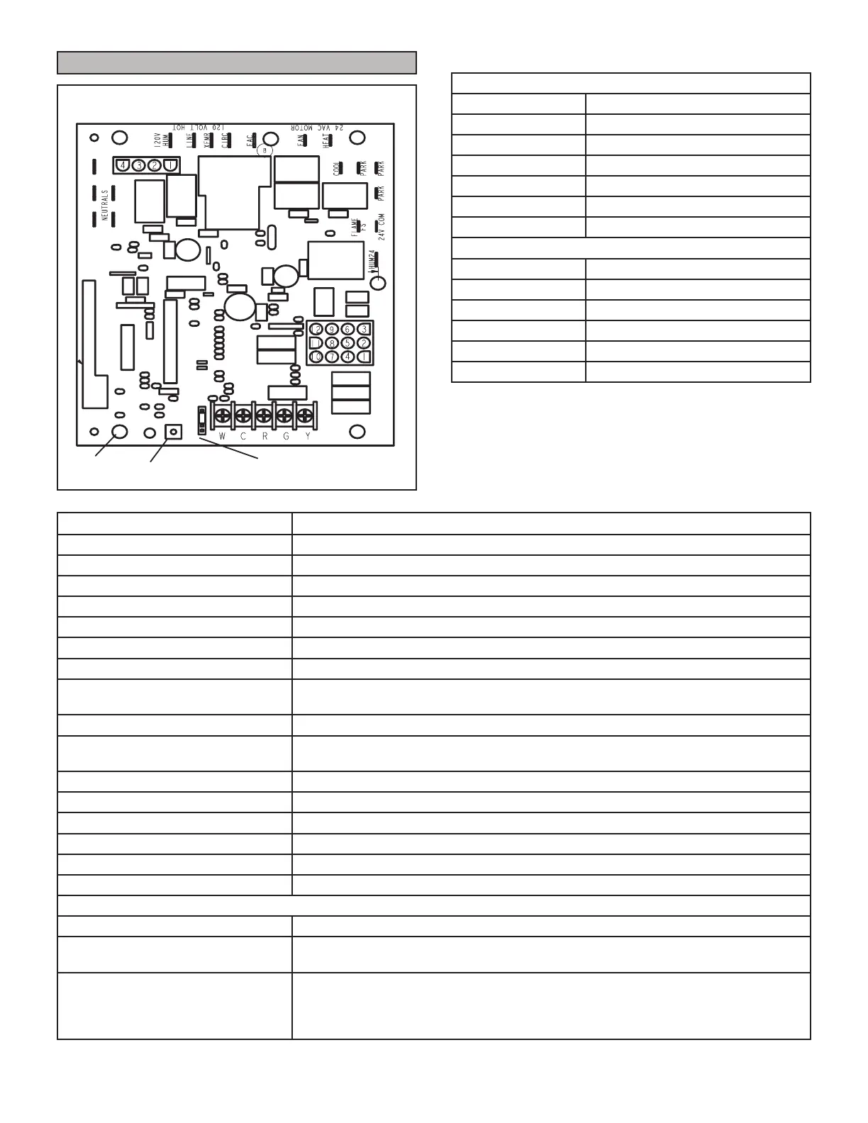
FIGURE 60
TABLE 10
1/4” QUICK CONNECT TERMINALS
120HUM Humidier 120VAC
LINE 120VAC
XFMR Transformer 120VAC
CIRC Indoor blower 120VAC
EAC Indoor air quality accessory 120VAC
NEUTRAL Common 120VAC
HUM24 Humidier 24VAC
3/16” QUICK CONNECT TERMINALS
COOL Cooling tap 24VAC
HEAT Heating tap 24VAC
FAN Continuous blower 24 VAC
PARK (no power) Park terminal for speed taps
FLAME / FS Flame Sense
24 COM Common 24VAC
RED LED Flash Code
2
Diagnostic Codes / Status of Furnace
O No power to control or board fault detected
Heartbeat
1
Normal Operation - Idle, Continuous Fan, Cool
Continuous Rapid Flash Call For Heat / Burner Operation
1 Reverse Line Voltage Polarity
2 Improper Earth Ground
3 Burner failed to light, or lost ame during heat demand
4 Low Flame Signal - check ame sensor
5
Watchguard - burner failed to light, exceeded maximum number of retries or
recycles.
6 Not Used
7
Primary or Secondary Limit Open or Watchguard Mode - Limit Switch Open longer
than 3 minutes
8 Rollout Switch Open
9 Pressure Switch failed to close or opened during heat demand
10 Watchguard - Pressure Switch opened 5 times during one heat demand
11 Pressure Switch stuck closed prior to activation of combustion air inducer
12 Flame Sensed without gas valve energized
13 Low Line Voltage
Notes
Note - 1 A ”Heartbeat” is indicated by a ”Slow Flash” - 1 sec on 1 sec o, repeating
Note - 2
Error codes are indicated by a “rapid ash” - the LED ashes X times at ½ second on ½
second o, remains o for 3 seconds then repeats.
Note - 3
Last 10 error codes are stored in memory including when power is shut o to the
unit. - To recall, press and release button, most recent will be displayed rst, LED o for 3
sec, then next error code is displayed, etc. To clear error codes, depress and hold button
longer than 5 seconds.
 Loading...