Page 48
G- Proper Ground and Voltage
A poorly grounded furnace can contribute to premature ig
nitor failure. Use the following procedure to check for
ground and voltage to the integrated control.
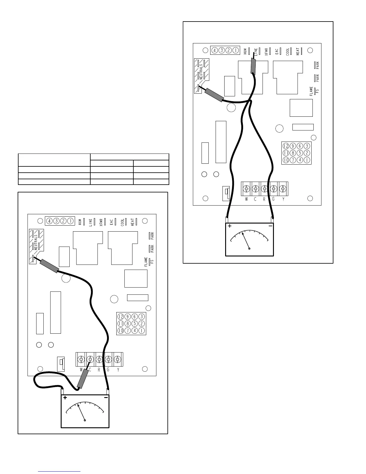
1 - Measure the AC voltage between Line Neutral (spade
terminals) and “C” terminal (low voltage terminal
block) on the integrated control. See figure 61. A wide
variation in the voltage between Line Neutral and “C”
as a function of load indicates a poor or partial ground.
Compare the readings to the table below. If the read
ings exceed the maximum shown in table 1, make re
pairs before operating the furnace.
2 - In addition, measure the AC voltage from Line Hot to
Line Neutral (spade terminals) on the integrated con
trol. See figure 62. This voltage should be in the range
of 97 to 132 Vac
TABLE 23
Furnace Status
Measurement VAC
Expected Maximum
Power On Furnace Idle 0.3 2
CAI / Ignitor Energized 0.75 5
Indoor Blower Energized Less than 2 10
AN2
GREEN
AN1
RED
CHECK VOLTAGE BETWEEN LINE NEU
TRAL AND LOW VOLTAGE “C” TERMINAL
FIGURE 61
FIGURE 62
AN2
GREEN
AN1
RED
CHECK VOLTAGE BETWEEN LINE HOT
AND LINE NEUTRAL
V-TYPICAL OPERATING CHARACTERISTICS
A-Blower Operation and Adjustment
NOTE- The following is a generalized procedure and
does not apply to all thermostat controls.
1 - Blower operation is dependent on thermostat control
system.
2 - Generally, blower operation is set at thermostat sub
base fan switch. With fan switch in ON position, blower
operates continuously. With fan switch in AUTO posi
tion, blower cycles with demand or runs continuously
while heating or cooling circuit cycles.
3 - Depending on the type of indoor thermostat, blower
and entire unit will be off when the system switch is in
OFF position.
B-Temperature Rise (Figure 63)
Temperature rise for EL195UH units depends on unit input,
blower speed, blower horsepower and static pressure as
marked on the unit rating plate. The blower speed must be
set for unit operation within the range of “TEMP. RISE °F”
listed on the unit rating plate.
 Loading...