Page 40
IV-HEATING SYSTEM SERVICE CHECKS
A-C.S.A. Certification
All units are C.S.A. design certified without modifications.
Refer to the ML196DFE Operation and Installation Instruc
tion Manual Information.
B-Gas Piping
CAUTION
If a flexible gas connector is required or allowed by
the authority that has jurisdiction, black iron pipe
shall be installed at the gas valve and extend outside
the furnace cabinet. The flexible connector can then
be added between the black iron pipe and the gas
supply line.
WARNING
Do not over torque (800 in-lbs) or under torque (350
in-lbs) when attaching the gas piping to the gas
valve.
Gas supply piping should not allow more than 0.5”W.C. drop
in pressure between gas meter and unit. Supply gas pipe
must not be smaller than unit gas connection.
Compounds used on gas piping threaded joints should be
resistant to action of liquefied petroleum gases.
C-Testing Gas Piping
IMPORTANT
In case emergency shutdown is required, turn off
the main shut‐off valve and disconnect the main
power to unit. These controls should be properly
labeled by the installer.
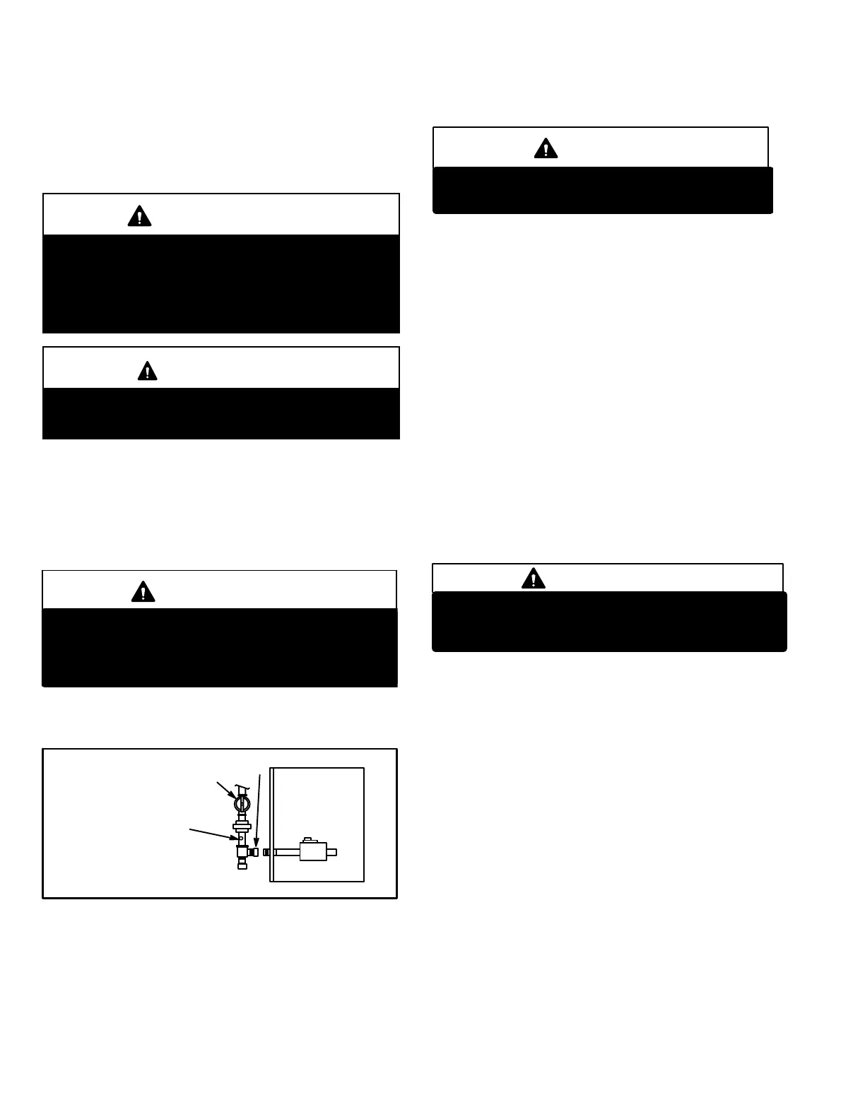
When pressure testing gas lines, the gas valve must be dis
connected and isolated. Gas valves can be damaged if
subjected to more than 0.5psig (14” W.C.). See figure 51.
FIGURE 51
MANUAL MAIN SHUT-OFF
VALVE WILL NOT HOLD
NORMAL TEST PRESSURE
CAP
FURNACE
ISOLATE
GAS VALVE
1/8” N.P.T. PLUGGED TAP
When checking piping connections for gas leaks, use pre
ferred means. Kitchen detergents can cause harmful corro
sion on various metals used in gas piping. Use of a specialty
Gas Leak Detector is strongly recommended. It is available
through Lennox under part number 31B2001. See Corp.
8411-L10, for further details.
WARNING
Do not use matches, candles, flame or any other
source of ignition to check for gas leaks.
D-Testing Gas Supply Pressure
When testing supply gas pressure, use the 1/8” N.P.T.
plugged tap or pressure post located on the gas valve to
facilitate test gauge connection. See figure 50. Check gas
line pressure with unit firing at maximum rate. Low pres
sure may result in erratic operation or underfire. High pres
sure can result in permanent damage to gas valve or over
fire.
On multiple unit installations, each unit should be checked
separately, with and without units operating. Supply pres
sure must fall within range listed in table 16.
E-Check Manifold Pressure
After line pressure has been checked and adjusted, check
manifold pressure. Move pressure gauge to outlet pres
sure tap located on unit gas valve (GV1).
Checks of manifold pressure are made as verification of
proper regulator adjustment.
IMPORTANT
For safety, connect a shut‐off valve between the
manometer and the gas tap to permit shut off of
gas pressure to the manometer.
Follow the steps below and use figure 52 as a reference. Gas
manifold Kit 10L34 provides additional components if need
ed.
1 - Connect the test gauge positive side “+“ to manifold
pressure tap on gas valve.
2 - Tee into the gas valve regulator vent hose and connect
to test gauge negative “-”.
3 - Start unit and let run for 5 minutes to allow for steady
state conditions.
4 - After allowing unit to stabilize for 5 minutes, record
manifold pressure and compare to value given in table
16.
5 - Shut unit off and remove manometer as soon as an ac
curate reading has been obtained. Take care to re
place pressure tap plug.
6 - Start unit and perform leak check. Seal leaks if found.
 Loading...