Page 43
IV-HEATING SYSTEM SERVICE CHECKS
A-C.S.A. Certification
All units are C.S.A. design certified without modifications.
Refer to the ML196UHE Operation and Installation Instruc
tion Manual Information.
B-Gas Piping
CAUTION
If a flexible gas connector is required or allowed by
the authority that has jurisdiction, black iron pipe
shall be installed at the gas valve and extend outside
the furnace cabinet. The flexible connector can then
be added between the black iron pipe and the gas
supply line.
WARNING
Do not over torque (800 in-lbs) or under torque (350
in-lbs) when attaching the gas piping to the gas
valve.
Gas supply piping should not allow more than 0.5” W.C.
drop in pressure between gas meter and unit. Supply gas
pipe must not be smaller than unit gas connection.
Compounds used on gas piping threaded joints should be
resistant to action of liquefied petroleum gases.
C-Testing Gas Piping
IMPORTANT
In case emergency shutdown is required, turn off
the main shut‐off valve and disconnect the main
power to unit. These controls should be properly
labeled by the installer.
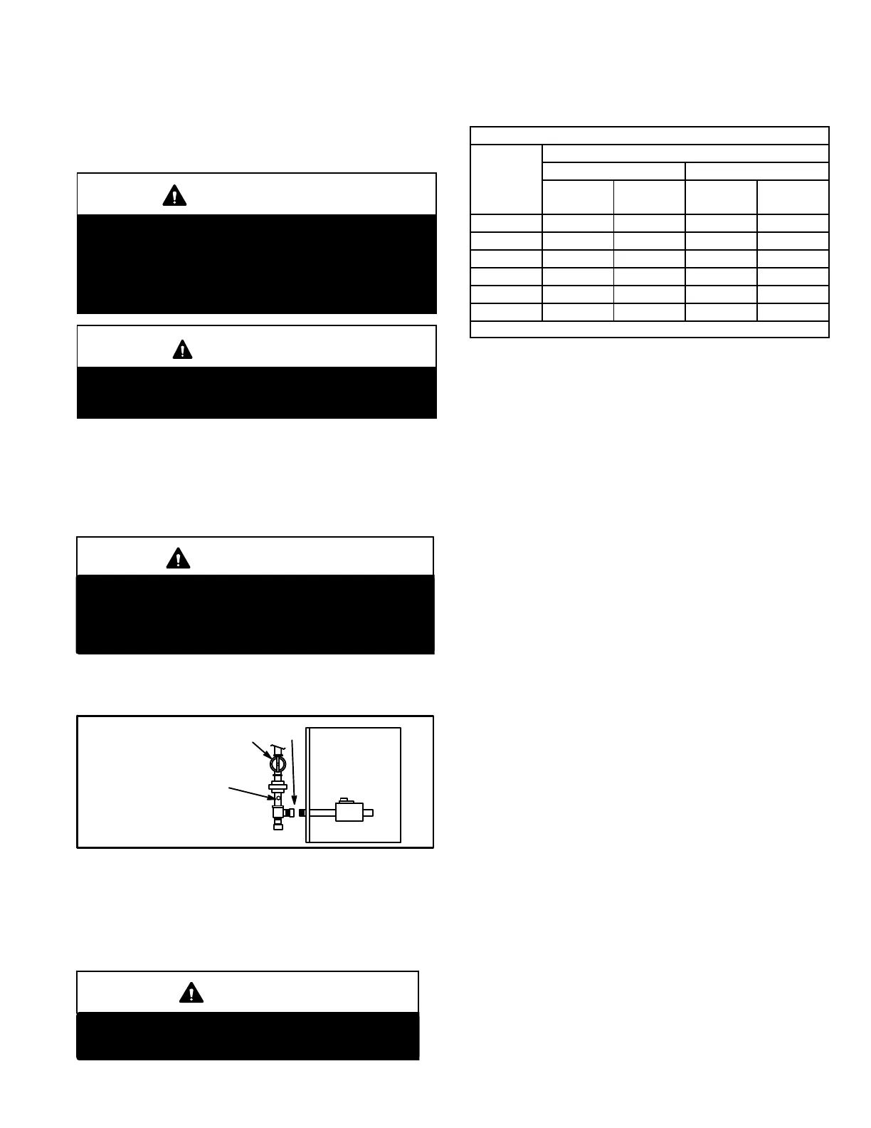
When pressure testing gas lines, the gas valve must be dis
connected and isolated. Gas valves can be damaged if
subjected to more than 0.5 psig (14” W.C.). See figure 55.
FIGURE 55
MANUAL MAIN SHUT-OFF
VALVE WILL NOT HOLD
NORMAL TEST PRESSURE
CAP
FURNACE
ISOLATE
GAS VALVE
1/8” N.P.T. PLUGGED TAP
When checking piping connections for gas leaks, use pre
ferred means. Kitchen detergents can cause harmful corro
sion on various metals used in gas piping. Use of a specialty
Gas Leak Detector is strongly recommended. It is available
through Lennox under part number 31B2001. See Corp.
8411-L10, for further details.
WARNING
Do not use matches, candles, flame or any other
source of ignition to check for gas leaks.
D-Testing Gas Supply Pressure
Gas Flow (Approximate)
TABLE 16
GAS METER CLOCKING CHART
ML196
Unit
Seconds for One Revolution
Natural LP
1 cu ft
Dial
2 cu ft
Dial
1 cu ft
Dial
2 cu ft
DIAL
-030 120 240 300 600
-045 80 160 200 400
-070 55 110 136 272
-090 41 82 102 204
-110 33 66 82 164
-135 27 54 68 136
Natural-1000 btu/cu ft LP-2500 btu/cu ft
Furnace should operate at least 5 minutes before check
ing gas flow. Determine time in seconds for two revolu
tions of gas through the meter. (Two revolutions assures a
more accurate time.) Divide by two and compare to time
in table 16. If manifold pressure matches table NO TAG
and rate is incorrect, check gas orifices for proper size and
restriction. Remove temporary gas meter if installed.
NOTE - To obtain accurate reading, shut off all other gas
appliances connected to meter.
Supply Pressure Measurement
When testing supply gas pressure, use the 1/8” N.P.T.
plugged tap located on the gas valve to facilitate test gauge
connection. See figure 7. Check gas line pressure with unit
firing at maximum rate. Low pressure may result in erratic
operation or underfire. High pressure can result in perma
nent damage to gas valve or overfire.
On multiple unit installations, each unit should be checked
separately, with and without other units operating. Supply
pressure must fall within range listed in table 18.
Manifold Pressure Measurement
Follow the steps below and use figure 56 as a reference. Gas
manifold Kit 10L34 provides additional components if need
ed.
1 - Connect the test gauge positive side “+“ to manifold
pressure tap on gas valve.
2 - Tee into the gas valve regulator vent hose and connect
to test gauge negative “-”.
3 - Start unit and let run for 5 minutes to allow for steady
state conditions.
4 - After allowing unit to stabilize for 5 minutes, record
manifold pressure and compare to value given in table
18.
5 - Shut unit off and remove manometer as soon as an ac
curate reading has been obtained. Take care to re
move barbed fitting and replace threaded plug.
6 - Start unit and perform leak check. Seal leaks if found.
 Loading...