26
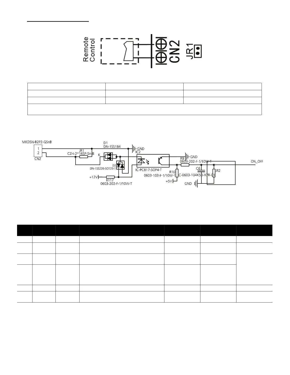
Remote Control Terminal
(ON-OFF, CN2, Short Connector JR1)
NOTE: Remove the short connector (JR1) when using the ON-OFF function.
Remote Switch Unit Status Demand Response Time
ON (close)
1
Unit is on. Within two (2) seconds
OFF (open)
2
Unit is o. Within two (2) seconds
1. Unit responds to demand; use the remote controller to select the required mode.
2. Unit will not respond to the demand from the remote controller.
NOTE: If the remote switch is o, but the remote controller is on, the CP code appear on the display board.
NOTE: The voltage of the port (CN2) is 12V DC; maximum current is 5mA.
4.5. Dial Codes
NOTE: The SW4 DIP switch is for certied service technical use only.
No. Dial Code Control
Scenario
Function ON OFF Note
1 SW1-2 1,2 Anti-cold blow protection option NO [Default] YES
2 SW1-3 1,2,3 Single cooling / heating and cooling options Cooling [Default] Cooling &
Heating
3 SW2-1 1 Compressor Running (demand working with
heat pump+ Electric heat)
Compressor
slower speed
[Default] Faster
Compressor
Only aects
compressor and
W1
4 SW2-1 2 Temperature dierential to activate rst stage
auxiliary heat(the GAP of T1 and Ts),Wire
controller demand with heat pump+Electric heat
working together
2°F (1°C) [Default] 4°F (2°C)
5 SW2-2 2 Electric heat on delay YES [Default]NO
6 SW2-3 2 Electric auxiliary heating delay to start time 30 minutes [Default] 15
minutes
Based on SW2-2
is ON
 Loading...