29
24V Input Terminal
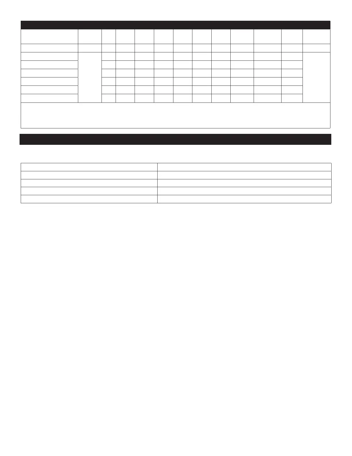
Mode Priority G Y1 Y/Y2 B W W1 W2 E/AUX DH/DS/BK Fan
speed
Display
Emergency heat 1 * * * * * * * 1 * Turbo 12
Heating zone control
2
* 1 0 1 0 * * 0 0 Low
13
Heating zone control * * 1 1 0 * * 0 0 Low
Heating zone control * * * * 1 * * 0 0 Low
Heating zone control * 0 0 * 0 1 0 0 0 Low
Heating zone control * 0 0 * 0 0 1 0 0 Low
Heating zone control * 0 0 * 0 1 1 0 0 Low
NOTE: 1: 24V signal
0: No 24V signal
*: 1 or 0.
The air handler unit will turn o if the 24V input cannot meet the table.
5. Connecting Cables
The power cord connection should be selected according to the following specications.
Table 4. Wire Gauge
Unit Gauge
1 drive 2 type (24K outdoor unit) 14
1 drive 3 type (30K outdoor unit). 14
1 drive 4 type (36K outdoor unit) 12
1 drive 5 type (48K outdoor unit) 10
 Loading...