13
Condensate Piping
Condensate formed during the heating and defrost
processes must be drained from heat pump units. Drain
holes are provided in the base of the units to ensure proper
drainage. Heat pumps must be raised when installed on a
concrete pad or the ground to allow drainage to occur. If
the heat pump unit is installed on wall mounting bracket,
insert the provided drain connector into one of the 1
inch (25 mm) drain holes and attached a eld-provided
insulated drain hose to the connector. Use eld-provided
rubber plugs to cover any unused drain holes (see “Figure
22. Condensate Drain” on page 13).
Drain
Connector
Chassis
Condensate Drain
(location varies per model)
Figure 22. Condensate Drain
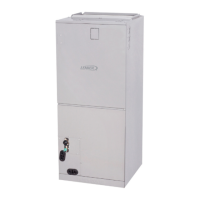
Securing the Outdoor Unit
Slab or Roof Mounting
Install the unit a minimum of 4 inches (102 mm) above the
roof or ground surface to avoid ice build-up around the
unit. Place the unit above a load bearing wall or area of
the roof that can adequately support the unit. Consult local
codes for rooftop applications.
CAUTION
Roof Damage!
This system contains both refrigerant and oil. Some
rubber roong material may absorb oil. This will cause
the rubber to swell when it comes into contact with oil.
The rubber will then bubble and could cause leaks.
Protect the roof surface to avoid exposure to refrigerant
and oil during service and installation. Failure to follow
this notice could result in damage to roof surface.
Securing Outdoor Unit to Slab, Frame, or Rails
If the outdoor unit is installed on a eld-provided slab or
frame, use lag bolts or equivalent to secure the outdoor
unit to the slab or frame.
Four Field-provided Anchor Bolts
Figure 23. Securing Outdoor Unit to Slab
Four Field-Provided
Anchor Bolts
Figure 24. Securing Outdoor Unit to Rails
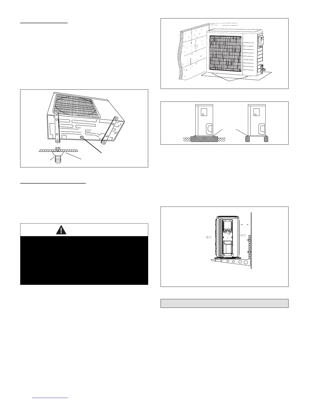
Securing Outdoor Unit To Hanging Brackets
If the outdoor unit is installed on eld-provided wall
mounting brackets, use lag bolts or equivalent to secure
the outdoor unit to the bracket. Minimum rear clearance
can be reduced to 6 inches (152 mm) when mounted
on brackets and with no obstructions on the other three
sides. Allow for condensate disposal when placing units
above one another.
Air Outlet
Air Inlet
6 in
152 mm
Figure 25. Securing Outdoor Unit to Brackets
Refrigerant Piping Connections
Field piping consists of two copper lines connecting the
outdoor unit to the indoor unit. “Table 3. Refrigerant Piping
and Indoor Unit Connection Sizes” lists the connection
sizes. The connections are made using the provided brass
are nuts at the end of the refrigerant piping connections.
1. Choose the correct pipe sizes for your application
using “Table 3. Refrigerant Piping and Indoor Unit
Connection Sizes” on page 14.
 Loading...