8
Torque Requirements for Caps and
Fasteners
When servicing or repairing HVAC components, ensure
the fasteners are appropriately tightened. “Table 1. Torque
Requirements” provides torque values for fasteners.
IMPORTANT
Only use Allen wrenches of sufcient hardness (50Rc -
Rockwell scale minimum). Fully insert the wrench into
the valve stem recess.
Service valve stems are factory-torqued from 9 ft.-lbs.
(12 N*m) for small valves, to 25 ft.-lbs. (34 N) for large
valves) to prevent refrigerant loss during shipping and
handling. Using an Allen wrench rated at less than 50Rc
risks rounding or breaking off the wrench, or stripping
the valve stem recess.
See the Lennox Service and Application Notes C-08-1
for further details and information.
Table 1. Torque Requirements
Parts
Recommended Torque
U.S. Newton-Meter- N
Service valve cap 8 ft.-lb. 11
Sheet metal screws 16 in.-lb. 2
Machine screws #10 27 in.-lb. 3
Compressor bolts 7 ft.-lb. 10
Gauge port seal cap 8 ft.-lb. 11
Indoor Unit Installation
CAUTION
In order to avoid injury, take proper precaution when
lifting heavy objects.
Unit Placement Considerations
AVOID
Do not install the unit in the following locations:
• Areas exposed to petrochemicals or petrochemical
products
• Areas exposed to salt or other corrosive materials or
caustic gases
• Areas exposed to extreme voltage variations (such as
factories
• Tightly enclosed areas that may impede service of the
unit
• Areas exposed to fossil fuels (such as oil or gas in
kitchens)
• Areas exposed to strong electromagnetic forces
• Areas exposed to acids or alkaline detergents
DO
• Place the unit so that it is not exposed to direct sunlight
• Ensure the structural ceiling can support the weight of
the unit
• Select a location where condensate line will have the
shortest run to a suitable drain per local codes
• Allow sufcient space around unit for proper operation
and maintenance
• Install unit a minimum of 3 feet (1m) away from any
antenna, power cord (line) radio, telephone, security
system, or intercom. Electrical interference and radio
frequencies from any of these sources may affect op-
eration
• Be sure to instruct customers how to properly operate
the unit (especially maintenance of air lter, and oper-
ation procedure) by having them carry out operations
themselves while looking at the manual provided with
the controller
Installation
1. Make sure that the structural ceiling or slab is able
to support the weight of the indoor unit. It may be
necessary to add extra support.
2. Install suspension rods in the structural
ceiling or concrete slab in a suitable location.
If the structural ceiling is constructed of concrete, install
anchors to accept four ⅜” threaded rods to suspend
the indoor unit. If the structural ceiling includes
wooden joists, use angle iron or Unistrut channel xed
securely in place to accept the ⅜” threaded rods.
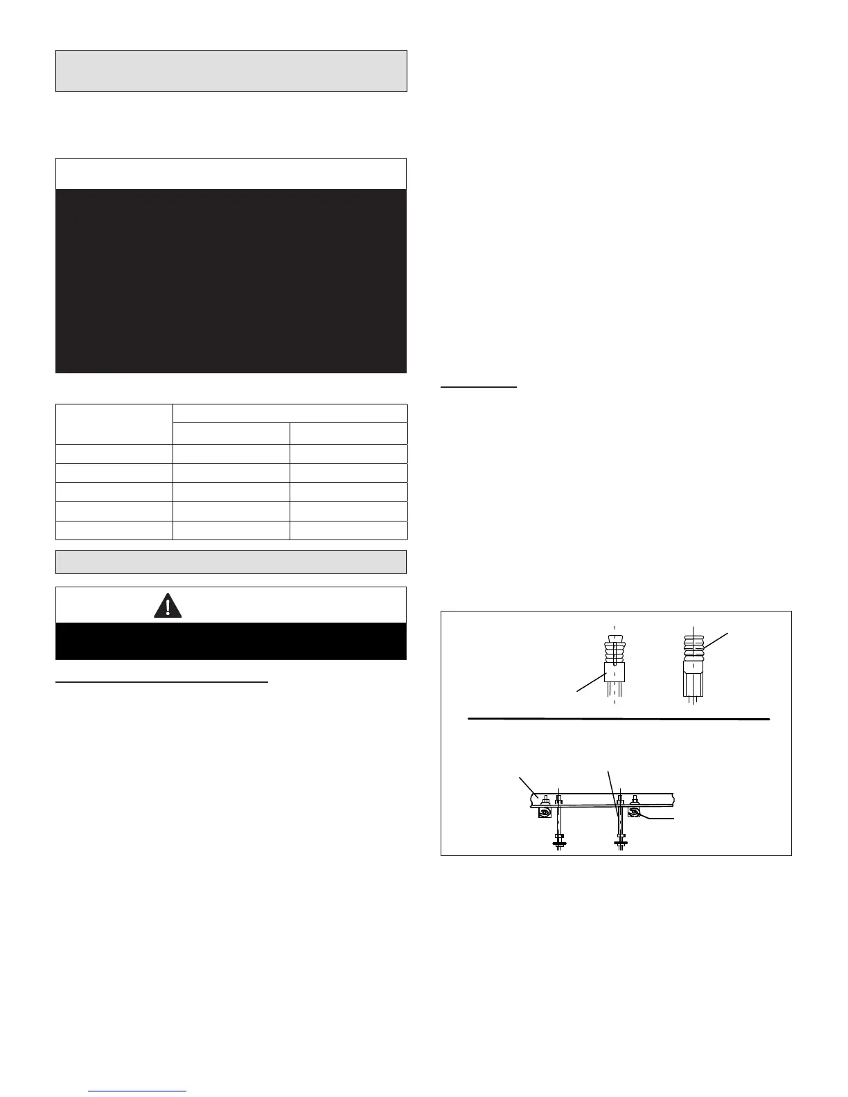
NOTE: Threaded rod is the ONLY acceptable method of
suspending the unit; do not use chains or straps.
See “Figure 6. Suspending Methods”.
ANGLE IRON
BOLTED IN
PLACE ACROSS
WOODEN JOISTS
WOODEN JOIST
⅜” THREADED
ROD
ANGLE IRON
ACROSS
WOODEN JOISTS
ANCHOR
CONCRETE CEILING
USING ANCHORS
⅜” THREADED
ROD
Figure 6. Suspending Methods
3. Slide one nut and one washer onto each threaded rod.
Use electrical tape to keep the washer from failing
off. Position the nuts slightly above the nal resting
place of the four suspension brackets. See”Figure 7.
Suspending Hardware”
 Loading...