Lennox Mini-Split Service Manual / Page 100
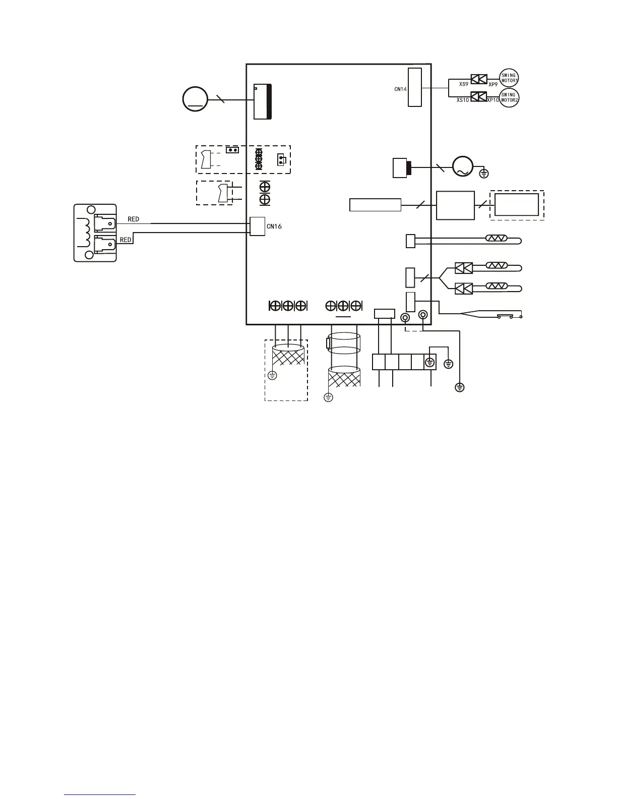
M33A036S4-1P & M33A048S4-1P Unit Wiring Diagram
Reactor
CN13
DISPLAY
BOARD
TO WIRE
CONTROLLER
10
T2
T1
CN6
4
BLACK
WHITE
CN10(CN10A)
M
PUMP
2
INDOOR UNIT
MAINBOARD
CN23
ON - OFF
Remote
Control
CN33
ALARM
Alarm
Output
CN15
M
FAN
5
RED(BROWN)
CN1
BLUE(BLACK)
L1
L2
Y/G
CN5
WATER LEVEL SWITCH
CN2
Q E P
To CCM
Comm.Bus
CN7
T2B
INDOOR COIL OUTLET TEMP.SENSOR
POWER
P1
Y/G
CN3
JR6
JR6
To OUTDOOR
Comm.Bus
S2
S1
P4
E Y X
Ferrite beadFerr
i
te bead
5
ROOM TEMP.SENSOR
INDOOR COIL TEMP.SENSOR
Note1:remove the JR6 jumper for
remote on/off control
Typical wiring diagram. Refer to
wiring diagram on the unit for
actual wiring.
 Loading...