Lennox Mini-Split Service Manual / Page 112
M22A and M33A
CAUTION
!
Make sure that drain piping is properly routed and
insulated to prevent both leaks and condensation.
1. Use a fi eld-provided hose clamp to secure the
drain line stub on the side of the cassette base
to a fi eld-supplied 1” (25 mm) drain line. NOTE -
Take care not to over-tighten the hose clamp as
this may damage the drain line stub.
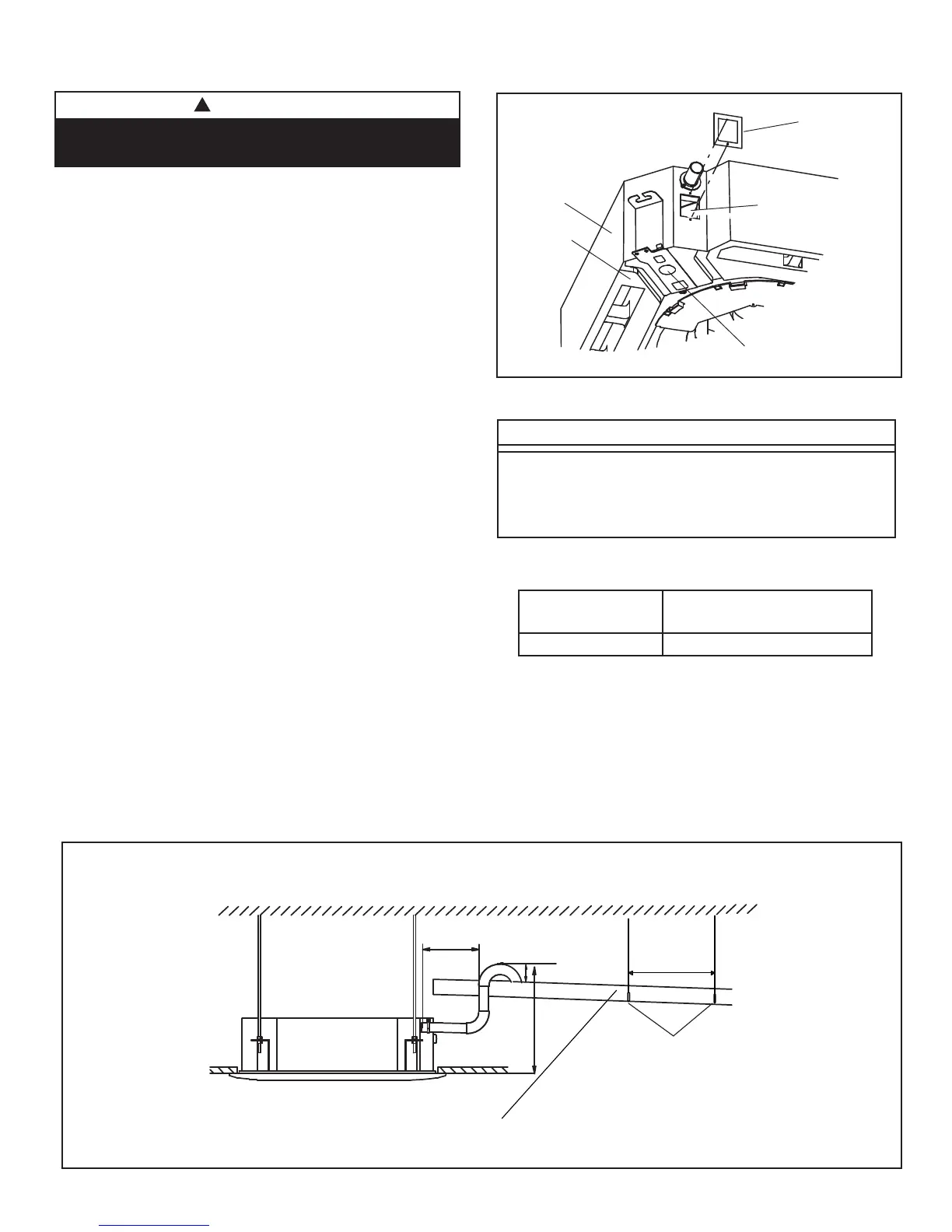
2. See fi gure below for applications using the unit’s
internal condensate pump to provide lift into a
drain. Ensure that the main drain line is properly
sloped (no less than 1/4 inch per foot (18 mm
per m)).
3. Drain should be as short as possible and should
not have any droops or kinks that would restrict
condensate fl ow and shall be approved resistant
pipe.
There must be a 2-inch (51 mm) space between
the end of the condensate drain and the fi nal
termination point (ground, open drain, etc.) to
ensure that the line will drain freely.
4. After system installation is complete, the
condensate drain line must be checked for leaks
and the condensate pumps must be checked
to ensure proper operation. This check is part
of the commissioning sequence. Pour water
into the evaporator drain pan to ensure proper
condensate drainage. See fi gure right. If a leak
is found, shut down power to the unit at once
and do not restore power to the unit until the
problem has been resolved.
IMPORTANT!
Drain should have a slope of at least ¼ inch per
foot and should be approved corrosion-resistant
pipe. You must confi rm operation of every drain and
pump in the system as part of the start-up process.
Test Condensate Drain
Drain Plug
Drain Pan
Cassette Base
Pour water
here for test
Cap
(Remove for test)
Cassette
Unit
7-7/8in.
2~3-15/16 in.
Drain
(slope of at least ¼ inch per foot)
Max. 27-1/2"
3 ft. (1 m)
SUPPORT
STRAPS
Indoor Unit Condensate Drain
Size
(Btuh)
Condensate Connections
All
1” (25 mm)
Condensate Piping Connections Table
 Loading...