22
NOTE: DIAGRAMS & ILLUSTRATIONS ARE NOT TO SCALE.
LENNOX HEARTH PRODUCTS • MERIT PLUS
®
DIRECT VENT GAS FIREPLACES (MPD33/35/40/45) • INSTALLATION INSTRUCTIONS
TABLE H
H
+H
1
Maximum H Maximum
V Minimum
feet
feet
feet
5
(1.524)
2 (0.610) 1 (0.305)
10
(3.048)
4 (1.219) 2 (0.610)
15
(4.572)
6 (1.829) 3 (0.914)
20
(6.096)
8 (2.438) 4 (1.219)
V + H + H
1
= 40 feet (12.2 m) Max.
H = 8 feet (2.438 meters) Max.
H + H
1
= 20 feet (6.096 meters) Max.
(meters)
(meters)
(meters)
H
+ H
1
Maximum
V Minimum
feet
feet
3
(0.914) Elbow Only
5
(1.524)
1 (0.305)
10
(3.048)
2 (0.610)
15
(4.572)
3 (0.914)
20
(6.096)
4 (1.219)
V +
H
+ H
1
= 40 feet (12.2 m) Max.
H
+ H
1
= 20 ft. (6.096 m) Max.
TABLE J
(meters)
(meters)
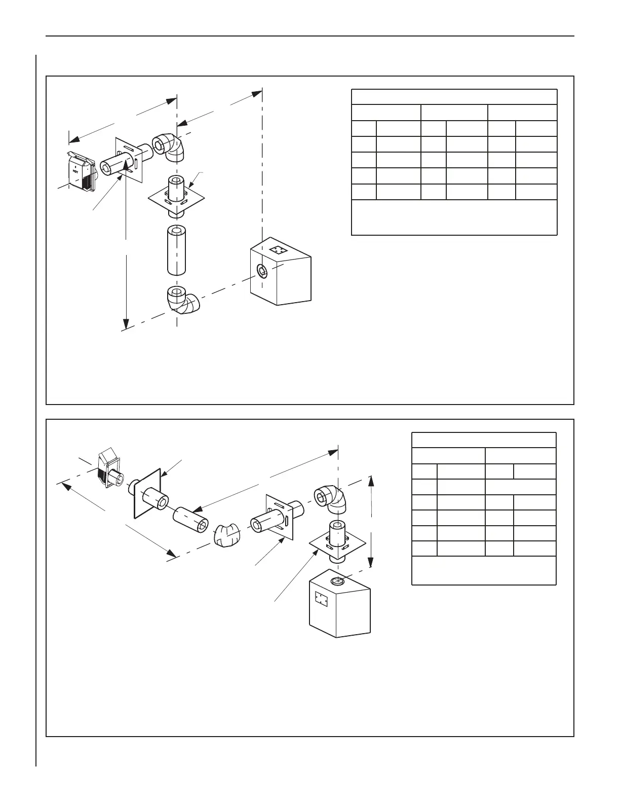
HORIZONTAL VENT FIGURES/TABLES (continued)
Figure 38: Rear Vent—TWO 90-DEGREE ELBOWS
Figure 39: Top Vent—TWO 90-DEGREE ELBOWS
Square termination (SV4.5HT-2) shown.
See Table 9 on Page 21 as an aid in venting component selection for a particular range
of exterior wall thicknesses.
Note: Install the U-shaped vent restrictor in any vent run with more than 8 ft of vertical
rise (See Page 13).
Square termination (SV4.5HT-2) shown.
Example: If 20 feet of (H) horizontal vent run is needed, then 4
feet minimum of (V) vertical vent will be required.
This table shows a 1 (V) to 5 (H) ratio. For every 1 foot of (V)
vertical, you are allowed 5 feet of (H) horizontal run, up to a
maximum horizontal run of 20 feet.
See Table 9 on Page 21 as an aid in venting component
selection for a particular range of exterior wall thicknesses.
Note: Install the U-shaped vent restrictor in any vent run with
more than 8 ft of vertical rise (See Page 13).
Example: If 20 feet of (H) horizontal vent run is
needed, then 4 feet minimum of (V) vertical vent
will be required.
This table shows a 1 (V) to 5 (H) ratio. For every
1 foot of (V) vertical, you are allowed 5 feet of (H)
horizontal run, up to a maximum horizontal run of
20 feet.
An elbow is acceptable as 1 foot of vertical
rise except where an elbow is the only vertical
component in the system. See Figure 36.
V
H
H
1
Ceiling Firestop/Spacer
SV4.5VF*
Wall Firestop/Spacer
SV4.5HF**
*When using Secure Flex, use
Ceiling Firestop/Spacer SF4.5VF.
**When using Secure Flex, use
Wall Firestop/Spacer SF4.5HF.
Wall Firestop/Spacer
SV4.5HF**
H
1
V
H
Ceiling
Firestop/Spacer
SV4.5VF*
Wall Firestop/
Spacer
SV4.5HF**
*When using Secure Flex , use
Ceiling Firestop/Spacer SF4.5VF.
**When using Secure Flex, use
Wall Firestop/Spacer SF4.5HF.
®
 Loading...