25
NOTE: DIAGRAMS & ILLUSTRATIONS ARE NOT TO SCALE.
LENNOX HEARTH PRODUCTS • MERIT PLUS
®
DIRECT VENT GAS FIREPLACES (MPD33/35/40/45) • INSTALLATION INSTRUCTIONS
Step 5. FIELD WIRING
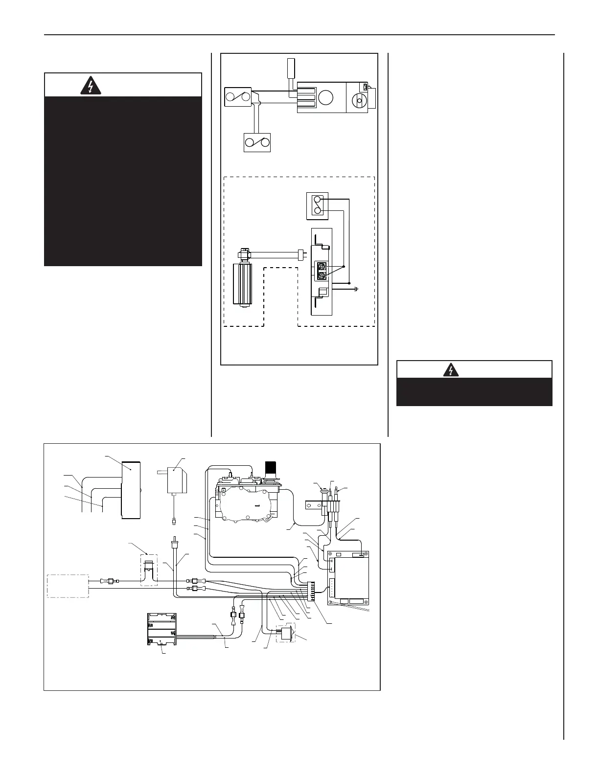
Figure 44: Wiring Diagram—Millivolt
Gas Valves
CAUTION
The ground supply lead must be
connected to the wire attached to
the green ground screw located
on the outlet box (see wiring
diagrams). Failure to do so
will result in a potential safety
hazard. The appliance must be
electrically grounded in accor-
dance with local codes or, in
the absence of local codes, the
National Electrical Code, ANSI/
NFPA 70
—latest edition (in
Canada, the current CSA C22-1
Canadian Electrical Code).
CAUTION: Label all wires prior to discon-
nection when servicing controls. Wiring
errors can cause improper and dangerous
operation.
ATTENTION: Au moment de l’entretien
des commandes, étiquetez tous les
fils avant de les débrancher. Des
erreurs de cáblage peuvent entraîner
un fonctionnement inadéquat et
dangereux.
Verify proper operation after servicing.
S’assurer que l’appareil fonctionne
adéquatement une fois l'entretien
terminé.
Refer to Section A for millivolt appliances
and Section B for electronic appliances. The
gas valve is set in place and pre-wired at the
factory on both models.
A. Millivolt Wiring (see Figure 44)
Millivolt units are not provided with any
factory-installed controls; therefore, one
of the optional control switches is required
to operate the unit (ON/OFF Wall Switch,
Unit-Mountable ON/OFF Switch*, Thermostat,
Remote Control). See the fi replace Care and
Operation Instructions for details.
[*If using a Unit-Mountable ON/OFF Rocker
Switch with an optional Style View Door, mount
the Rocker Switch on the door instead of the
unit.]
1. If installing an ON/OFF wall switch or
thermostat, mount it in a convenient
location on a wall near the fi replace.
2. Wire the control switch within the millivolt
control circuit using the 15 feet of 2
conductor wire supplied with the unit.
Note: The supplied 15 feet of 2 conductor
wire has one end of each conductor
connected to the gas valve circuit and the
other end of each conductor placed loose
inside the bottom compartment.
CAUTION
In millivolt systems, do NOT connect
a Wall Switch to a 120V power supply.
B. Electronic Wiring (Figures 45 & 46)
One of the following optional controls
also may be used: ON/OFF Wall Switch,
Thermostat, Remote Control (see fi replace
Care and Operation Instructions for details.).
Note: Electronic models must be connected
to the main power supply.
1. Route a 3-wire 120Vac 60Hz 1ph power
supply to the appliance junction box.
2. Remove the electrical inlet cover plate
from the side of the unit by removing the
plate’s securing screws (see Figure 12,
Page 11).
3. Remove the cover plate knockout; then
feed the power supply wire through
the knockout opening and into the unit
junction box.
4. See Figures 45 & 46. Connect the black
power supply wire to the lower outlet’s
red pigtail lead.
Connect the white power supply wire to
the outlet’s common terminal.
5. Connect the ground supply wire to the
pigtail lead attached to the outlet’s green
ground screw.
TP-TH
TP
TH
APPLIANCE- MOUNTED
ON/OFF SWITCH
(OPTIONAL)
BK/W(1)
BK/W(1)
WALL-MOUNTED ON/OFF SWITCH (OPTIONAL)
THERMOSTAT (OPTIONAL)
JUNCTION BOX
BLACK
W
GR
120 V
AC
WALL MOUNTED CONFIGURATION FOR FAN SWITCH (OPTIONAL)
BK
R
THERMOPILE
GAS VALVE
FAN
(OPTIONAL)
Figure 45: Wiring Diagram—Electronic Gas Valves
P/N 580491-01
JUNCTION BOX
120V AC
REMOTE RECEIVER
ON/OFF SWITCH
WALL SWITCH
LIMIT SWITCH
B-VENT MODELS
ONLY
AC/DC
POWER
ADAPTOR
HOT
NEUTRAL
OPTIONAL
GROUND
BATTERY HOLDER
DFC WIRE HARNESS
SPARK WIRE CABLE
PILOT GROUND WIRE
PILOT
SENSOR
CABLE
HOOD
IGNITER ROD
FLAME SENSOR
PILOT TUBE
OPTIONAL CPI SWITCH
OFF (O) = INTERMITTENT PILOT MODE
ON (-) = STANDING PILOT MODE
PROFLAME DFC BOARD
PROFLAME VALVE
ELECTRONIC PILOT ASSEMBLY
B = BLACK
BR = BROWN
GY = GRAY
PU = PURPLE
R = RED
BL = BLUE
G = GREEN
O = ORANGE
W = WHITE
Y = YELLOW
WIRING COLOR CODE
B
B
B
R
R
W
W
B
B
B
B
BL
BL
G
G
O
Y
Y
R
R
Y
W
G
G
O
SCHEMATIC REPRESENTATION ONLY
 Loading...