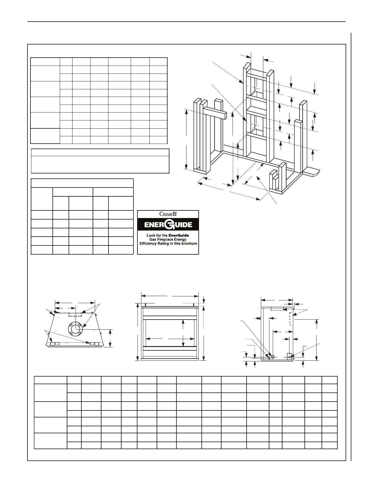
11
NOTE: DIAGRAMS & ILLUSTRATIONS ARE NOT TO SCALE.
LENNOX HEARTH PRODUCTS • MERIT PLUS
®
DIRECT VENT GAS FIREPLACES (MPD33/35/40/45) • INSTALLATION INSTRUCTIONS
.oNledoM A B C D E F G H J K L M N
.ni 8/133 8/103 71 2/172 8/133 8/591 2/112 4/301 61/316 3 23/118 3/22 31
mm 148 567 234 996 148 894 645 372 371 67 212 07 033
MPD35
.ni 8/153 8/123 91 2/192 8/153 61/1112 8/742 1 61/72 9 3 9 3 61
mm 298 618 384 947 298 155 236 613 022 67 022 67 604
MPD40
.ni 8/104 8/173 42 2/143 8/104 61/1162 8/792 1 61/514 9 3 9 3 61
mm 9101 349 016 678 9101 876 957 973 022 67 022 67 604
MPD45
.ni 8/104 8/173 42 2/193 8/154 61/1162 8/743 61/771 9 3 9 3 61
mm 6411 349 016 3001 6411 876 688 344 022 67 022 67 604
MPD33
A
B
D
7
(178)
5-1/8
12-1/8
(308)
10-1/2
(
267
)
C
VENT FRAMING:
TOP VENT WITH ONE
90° ELBOW
VENT FRAMING:
REAR VENT WITH
NO ELBOWS
Framing should be
constructed of 2x4
or larger lumber.
Inches (mm)
E
(130)
(130)
7
(308)
(178)
1/2
A
5-1/8
12-1/8
Dimension “E” is the required framing depth when the
finish material (drywall) thickness is 1/2 in. (13mm).
.oNledoM A B C D E
.ni 4/133
mm
.ni
mm
MPD35
.ni 4/153 4/153 61/1112 4/393 61
mm 598 598 155 0101 604
MPD40
.ni 4/104 4/104 61/1162 4/344 61
mm 2201 2201 876 7311 604
MPD45
.ni 4/154 4/104 61/1162 4/344 61
mm 9411 2201 876 7311 604
— 37 3/4 12 7/833 1/4
— 959 327845 845
19 5/8 — 12 7/833 1/4 33 1/4
498 — 327845 845
MPDR33
MPDT33
G
H
Concentric Flue:
Flue
4-1/2 in. (114 mm);
Combustion Air
7-1/2 in. (190 mm).
See Notes [1] and [2].
Rear/Side
Framing
Spacers
Notes:
[1] MPD models have a top and rear vent. MPDR models
have a rear vent only. MPDT models have a top vent only.
[2] Collars protrude one inch on MPDT33 and MPDR33 models.
J
F (rear vent
models only)
N
1/2 (13)
1-5/8 (42)
L
K
Gas Inlet (either
side and bottom)
Electrical Inlet
2-3/4" x 2"
(70 x 51 mm)
Cover Plate
with Knockout
M
See Note [2].
6 (152)
1-3/8 (35)
Optional Electrical Inlet
Knockout requiring a
Field-Provided Junction
Box (either side)
E
B
D
C
3 (76)
A
Header
Spacing
Top
Standoffs
Vertical Venting through the Ceiling
Frame ceiling opening: Use a plumb line from the ceiling above the appliance to locate center of the vertical run. Cut and/or frame an opening,
10 1/2 in. x 10 1/2 in. (267 mm x 267 mm) inside dimensions, about this center mark (see Figure 17).
Notes
Diagrams, illustrations and photographs are not to scale. Consult installation
instructions. Product designs, materials, dimensions, specifications, colors,
and prices are subject to change or discontinuance without notice.
Thermal Efficiency (%)
Fireplace
Model
Natural Gas Propane
AFUE EnerGuide
(P4)
AFUE EnerGuide
(P4)
MPDT33
62 45 64 49
MPDR33
61 53 64 55
MPD35
62 53 60 55
MPD40
67 59 67 60
MPD45
67 59 67 59
Based on CSA P.4.1-09
Figure 12: Fireplace and Framing Specifications
Framing
 Loading...