39
NOTE: DIAGRAMS & ILLUSTRATIONS ARE NOT TO SCALE.
LENNOX HEARTH PRODUCTS • MERIT PLUS
®
DIRECT VENT GAS FIREPLACES (MPD33/35/40/45) • INSTALLATION INSTRUCTIONS
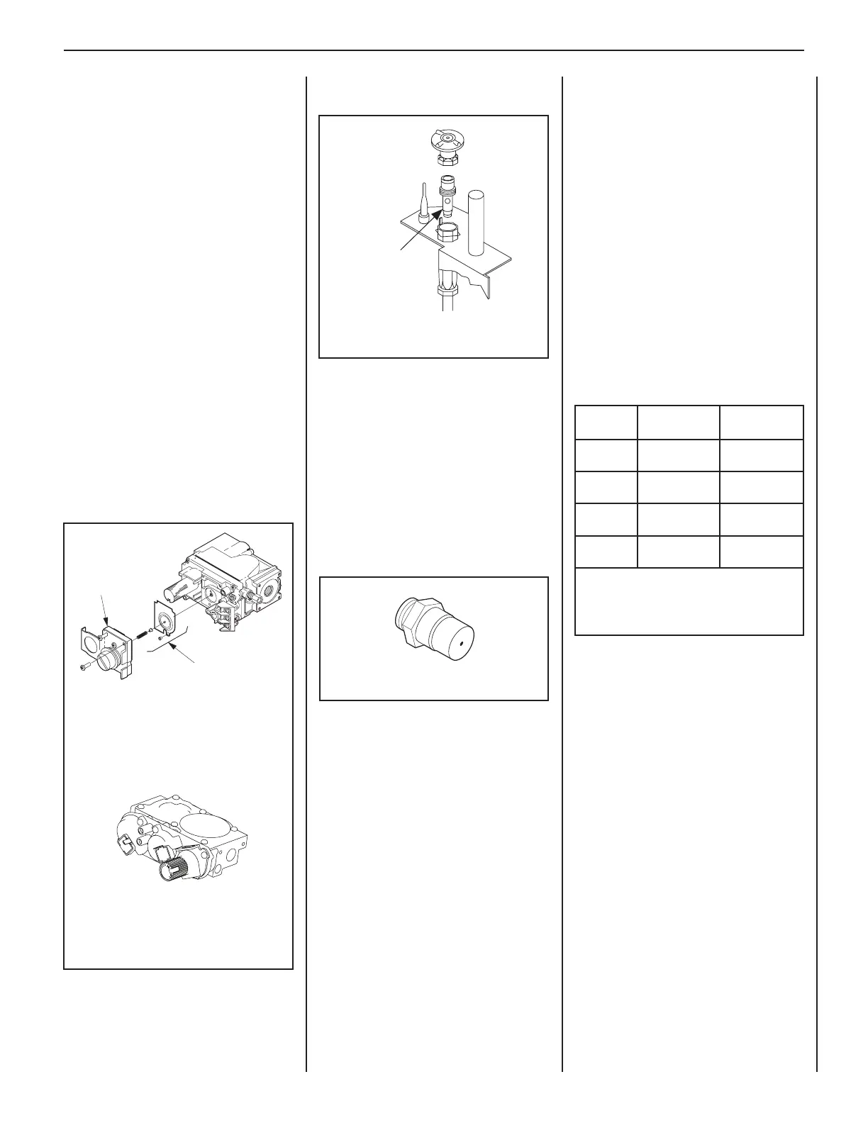
Step 9. Refer to Figure 64 and replace the
pilot orifice.
Remove the pilot hood assembly to access
the hexed pilot orifice. Remove and replace
the orifice with the one provided with the kit.
Exercise extreme care to prevent damage to
or breakage of the igniter assembly.Step 10.
Refer to Figure 64 and replace the burner
orifice.
A. Remove the orifice from the manifold and
replace it with the one provided in the kit. See
the following table for orifice sizes for natural
and propane models. Figure 65 illustrates
the orifice.
Use pipe joint compound or Teflon tape on
all pipe fittings before installing (ensure
propane resistant compounds are used in
propane applications, do not use pipe joint
compounds on flare fittings).
B. Retrieve the burner and hold the venturi
tube above the orifice. Place the shutter
adjusting rod in the propane slot of the
shutter arm (see Figure 60 on Page 34).
Set the burner assem bly into its position
and secure the trapezoidal plate with the two
screws previously removed.
C. Reinstall the baffle with the two baffle
securing screws.
Step 11. Reassemble the remaining
components by reversing the procedures
outlined in the Steps 1–7.
Step 12. Attach the conversion label provided
in the conversion kit next to the rating plate
on the appliance.
Step 4. Carefully remove the logs. Exercise
care so as not to break the logs.
Step 5. Refer to Figure 2 on Page 4.
A. Remove the sub floor.
B. Remove the two (2) screws securing the
burner assembly.
C. Remove the burner assembly with
attached venturi tube.
Millivolt and Electronic Ignition
System Appliances
Step 6. SIT Systems—Refer to Figure 63
and the instructions provided with the SIT
Regulator Conversion Kit. Using a Torx
T20 driver (with 1/4 in. shank and center
hole) or slotted screwdriver, remove and
discard the pressure regulator mounting
screws (two screws for electronic models,
three screws for millivolt models), pressure
regulator tower, the diaphragm assembly
(if applicable) and the spring. Discard all
removed components.
Step 7. Install the new pressure regulator
assembly using the supplied screws as
shown in Figure 63. Tighten the screws to
25 in-lb..
Step 8. Install the enclosed identification
label to the valve body where it can be easily
seen.
Figure 64: Electronic Pilot
Step 13. Turn on gas supply and test for gas
leaks (refer to Page 27).
Step 14. Relight the main burner. The lighting
instructions can be found on the lighting
label in the control compartment or in the
Care and Operation Manual provided with
the appliance. Verify proper burner ignition
and operation. See Burner Adjustments and
Burner Flame Appearance on Page 33.
Inspect the pilot system for proper flame. The
pilot flame should engulf the flame sensor as
shown in Figure 50 on Page 27.
Step 15. Using a manometer, test the inlet
and manifold gas pressures. See Table 3 on
Page 4.
ALWAYS TEST PRESSURES WITH THE
VALVE REGULATOR CONTROL AT THE
HIGHEST SETTING.
Figure 65
Figure 63
Pressure
Regulator
Remove
These
Components
Electronic Valve
Millivolt Valve
Model
Series
Nat.Gas
drill size (inches)
Propane
drill size (inches)
MPDT33
MPDR33
#37 (0.104 in.)*
24M10•
0.048 in.
99K78•
MPD35
#45 (0.0820 in.)*
39L66•
#55 (0.0520 in.)*
19L52•
MPD40
#38 (0.1015 in.)*
99K76•
0.063 in.
21L01•
MPD45
#47 (0.0785 in.)*
99K74•
#52 (0.0635 in.)*
37G00•
Table 10: Burner Orifice Sizes
Elevation 0–4500 ft ( 0–1372 m)
* Standard size installed at factory
• Part /Cat. Number
 Loading...