Page 14
MS8C / MS8H (208-230V)
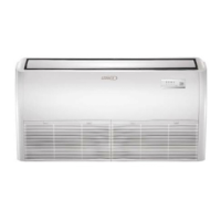
CONDENSATE LINE
DRAIN CAP
CONDENSATE LINE
DRAIN PAN
OUTLET
CLAMP
1. Locate the condensate line and the drain cap
located on unit.
2. Remove the clamp which secures the condensate
line to the drain outlet and pull the line to remove it.
3. Apply moderate force to pull off the drain cap from
the unit.
CLAMP HOOK
CLAMP HOOK
LATCH
IMPORTANT — Keep horizontal runs of condensate line external
to unit as short as possible. Condensate line should be properly
sloped to ensure proper drainage.
4. Re-install the drain cap on the opposite side
drain outlet.
5. Slide the condensate line over the opposite
drain outlet and use the clamp to secure the
line.
CLAMP
DRAIN CAP
REAR VIEW OF UNIT
REAR VIEW OF UNIT
REAR VIEW OF UNIT
CHANGING CONDENSATE DRAIN LOCATION
(IF NECESSARY)
FIGURE 18
CONDENSATE DRAIN LINE INSTALLATION
IMPORTANT !
Drain should have a slope of not less than ¼ inch per
foot and be approved corrosion resistance pipe.
1. Confirm proper slope (not less than 1/4 inch per foot)
and routing of condensate lines to ensure moisture is
drained away from the indoor unit (see page 12).
2. Drain should not have any droops or kinks that would
restrict condensate flow and shall be approved
resistant pipe.
3. Condensate drains should be ran as short as possible.
4. Once installation of drain is complete, pour water into
the evaporator drain pan to ensure proper condensate
drainage. If condensate will not properly drain from
evaporator pan, a condensate pump should be added
to system.
5. Confirm proper insulating, taping and bundling of
refrigeration lines, main power lines and drain line (see
page 16).
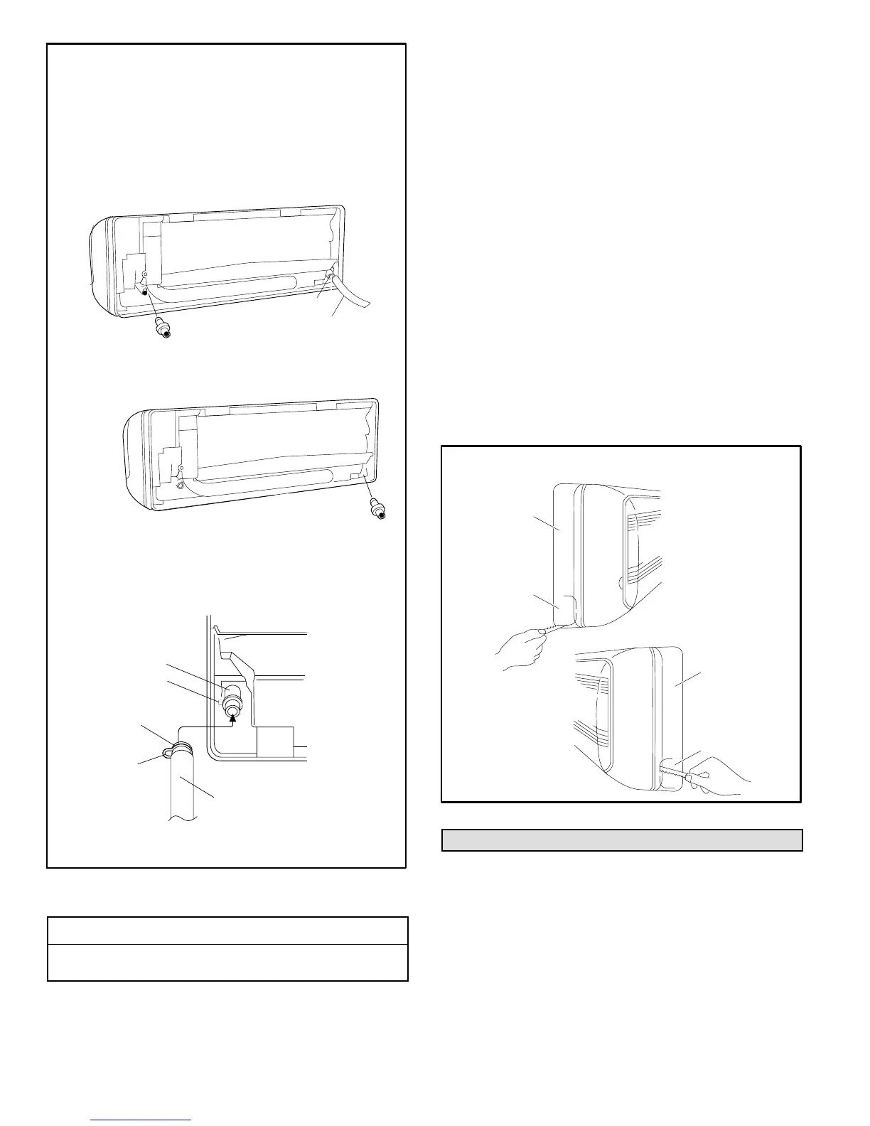
PREPARING INDOOR UNIT FRAME FOR LEFT- OR
RIGHT-SIDE EXIT OF UTILITY BUNDLE
1. Right- or Left-Side Utility Bundle Exit — Cut out the
corner of the right/left plastic cabinet with a hacksaw or
similar tool (A or B).
2. Right-Rear or Left-Rear Utility Bundle Exit — The
corner of the plastic cabinet does not need to be
modified.
B
A
RIGHT-SIDE
TUBING OUTLET
PLASTIC
CABINET
LEFT-SIDE
TUBING OUTLET
PLASTIC
CABINET
LEFT- OR RIGHT-SIDE UTILITY EXIT
FIGURE 19
Indoor Unit Cable Connections
NOTE — Stranded wire must be used to connect the
outdoor unit to the indoor unit. The stranded wire is
necessary to ensure proper system communication and
operation.
1. Route the cable (4-conductor, stranded wire, line
voltage, sized per National Electric Code) through the
wall sleeve. Refer to unit nameplate for rated voltage.
 Loading...