Page 7
Corp. 1244-L9
TABLE 3. OUTDOOR UNIT DIMENSIONS — INCHES (MILLIMETERS)
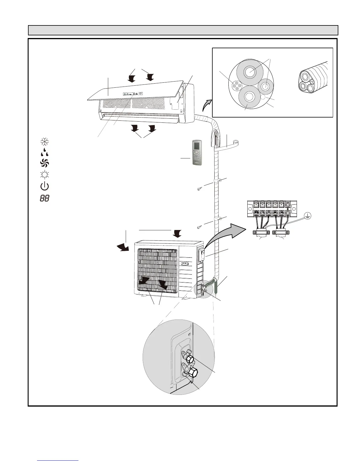
Typical System Component Setup
INDOOR UNIT
RETURN AIR
SUPPLY AIR
WIRELESS REMOTE
CONTROL
DISPLAY
INDICATORS
COOL
DRY
FAN
HEAT
RUN
TEMPERATURE SETTING,
INDOOR AMBIENT TEMPERATURE
OR ERROR CODE
AIR IN
AIR OUT
A
B
C
D
E
F
H
I
A. Remote control
B. Front panel
C. Filters
D. Guide louver with display
E. Line set (wrapped in foam insulation)
F. UV-rated tape (field-provided)
G. Wiring (field-provided)
H. Condensate drain line (field-provided)
(wrapped in foam insulation). Recommend
installation of a vent when making long
horizontal runs on condensate line.
I. 3-way service valve
J. Access cover for power and control wiring
connections
K. Indoor unit wiring connections (under
access plate)
OUTDOOR UNIT
TERMINAL BLOCK
TO INDOOR
UNIT
TO POWER
SUPPLY
3-WAY SERVICE VALVE
(FLARE CONNECTION)
2-WAY SHUT-OFF VALVE
J
OUTDOOR UNIT (AIR
CONDITIONER OR HEAT
PUMP)
K
REFRIGERANT LINE SET, CONDENSATE LINE
AND INDOOR / OUTDOOR CABLE
G
H
D
L
TAPE
IMPORTANT - The refrigerant
metering device for this system is
located in the outdoor unit. This
makes it necessary to insulate
the refrigerant lines individually to
prevent sweating.
NOTE — temperature can be
displayed in either Fahrenheit or
Celsius.
TYPICAL COMPONENT SETUP
FIGURE 1
 Loading...